Battery controlling device

a battery control and battery technology, applied in secondary cells, battery servicing/maintenance, instruments, etc., can solve the problems of deterioration of the performance originally possessed by the secondary battery, inability to fully exert the performance, and extreme difficulty in precisely measuring the temperature in the vicinity of an electrolysis solution or an electrode directly related to unevenness of ions, so as to prevent deterioration of the performance of the secondary battery.

Active Publication Date: 2019-02-12
HITACHI VEHICLE ENERGY
View PDF15 Cites 0 Cited by
  • Summary
  • Abstract
  • Description
  • Claims
  • Application Information

AI Technical Summary

Benefits of technology

[0007]According to the present invention, deterioration of the performance of the secondary battery can be reliably prevented even in a case in which the temperature is largely changed during usage of the secondary battery.

Problems solved by technology

If a secondary battery such as a lithium-ion battery is subjected to continuous charge / discharge with a high current for a long period of time, an internal resistance value is increased, performance is deteriorated, and the performance originally possessed by the secondary battery cannot be fully exerted.
It is general to acquire the temperature of the battery by attaching a thermocouple or a thermistor to a surface of the battery, and it is extremely difficult to precisely measure the temperature in the vicinity of an electrolysis solution or an electrode directly related to unevenness of ions.
However, if the temperature is changed due to heat generation of the battery caused by charge / discharge, a cooling medium, or a cooling wind, a temperature difference is caused between the inside and outside the battery, and it becomes difficult to precisely estimate the temperature in the battery.
As a result, the charge / discharge of the battery may be excessively restricted due to the difference between a measured value of the battery temperature and the actual temperature in the battery, or charge / discharge may not be appropriately restricted, which may lead to resistance increase and unsatisfaction of an expected life.

Method used


Image

  • Battery controlling device
  • Battery controlling device
  • Battery controlling device

Examples


Embodiment Construction

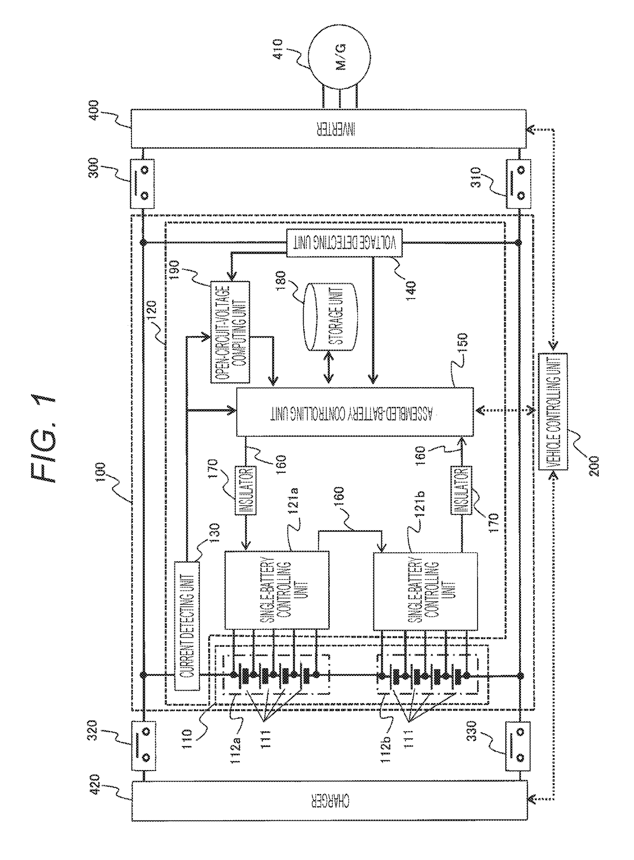
[0016]Hereinafter, an embodiment of the present invention will be described based on drawings. In the following embodiment, a case in which the present invention is applied to a battery system, which constitutes an electric power source of a hybrid vehicle (HEV), is taken as an example for description.

[0017]Moreover, in the following embodiment, a case in which a lithium-ion battery is employed as a secondary battery is taken as an example for description. However, other than that, a nickel-hydrogen battery, a lead battery, an electric double-layer capacitor, a hybrid capacitor, etc. can be used. Note that, in the following embodiment, an assembled battery is formed by serially connecting single batteries. However, an assembled battery may be formed by serially connecting parallelly-connected single batteries, or an assembled battery may be formed by parallelly connecting serially-connected single batteries.

[0018]FIG. 1 is a block diagram showing a battery system 100 according to th...


PUM

PropertyMeasurementUnit
timeaaaaaaaaaa
timeaaaaaaaaaa
timeaaaaaaaaaa

Abstract

A battery controlling device includes: a voltage detecting unit configured to detect a closed-circuit voltage of a secondary battery; an open-circuit-voltage computing unit configured to compute an open-circuit voltage of the secondary battery; and an assembled-battery controlling unit configured to discriminate whether a computed value computed based on a voltage difference between the closed-circuit voltage and the open-circuit voltage of the secondary battery in a continuous predetermined period is exceeding a permissible value determined in advance or not. If the computed value is exceeding the permissible value determined in advance, the assembled-battery controlling unit outputs a signal that carries out charge / discharge restriction of the secondary battery.

Description

TECHNICAL FIELD[0001]The present invention relates to a battery controlling device that controls charge / discharge of a secondary battery.BACKGROUND ART[0002]Secondary batteries used in vehicle-mounting uses, etc. are expected to be used with high currents. If a secondary battery such as a lithium-ion battery is subjected to continuous charge / discharge with a high current for a long period of time, an internal resistance value is increased, performance is deteriorated, and the performance originally possessed by the secondary battery cannot be fully exerted. Therefore, in order to prevent such performance deterioration, PTL 1 discloses a battery controlling method that accumulates evaluation values, which indicate the deterioration degree of a battery caused by continuance of discharge of the battery, and, if the accumulated value thereof exceeds a predetermined permissible value, restricts discharge of the battery.[0003]In the battery controlling method disclosed in this PTL 1, whet...

Claims


Application Information

Patent Timeline
Patent Type & Authority Patents(United States)
IPC IPC(8): H02J7/00H02J7/16H02J7/04G01R31/36H01M10/44H01M10/42H01M10/48
CPCB60L58/10H02J7/0068G01R31/36H01M10/425H01M10/44H01M10/48H01M10/482H02J7/00H02J7/007H01M10/441H01M2220/20Y02T10/70Y02E60/10
Inventor MORIKAWA, HIROSHIAOSHIMA, YOSHINORINAITOH, MASASHI
Owner HITACHI VEHICLE ENERGY
Why Eureka
Try Eureka