Connecting System For Surface Coverings

a technology of connecting system and surface covering, which is applied in the field of surface covering, can solve the problems of affecting the installation and use of the floor system, so as to achieve convenient and fast installation and flexibility, improve the ease of installation, and facilitate the connection to other planks

Inactive Publication Date: 2009-09-10
MANNINGTON MILLS
View PDF19 Cites 90 Cited by
  • Summary
  • Abstract
  • Description
  • Claims
  • Application Information

AI Technical Summary

Benefits of technology

[0015]Another feature of the present invention is to provide a flooring system for flooring planks and other surface-coverings that do not require any connecting accessories such as an insert, spline, metal clip, or the like, and which permits easy and fast installation and flexibility.
[0016]Still another feature of the present invention is to provide a flooring system that has significant improvements with respect to ease of installation at confined areas, and includes a foolproof installation design and technique.
[0017]Another feature of the

Problems solved by technology

Current floor systems have suffered, however, from disadvantages.
One disadvantage experienced with current floor systems is that if each of the side edges of a plank includes a mechanical locking tongue or groove, once one of the side edges is connected to another similar plank, it is difficult to connect the other side edges of the plank with yet another similar plank.
This problem particularly accentuates itself while installing a click system floor in a very limited-free-sp

Method used


Image

  • Connecting System For Surface Coverings
  • Connecting System For Surface Coverings
  • Connecting System For Surface Coverings

Examples


Embodiment Construction

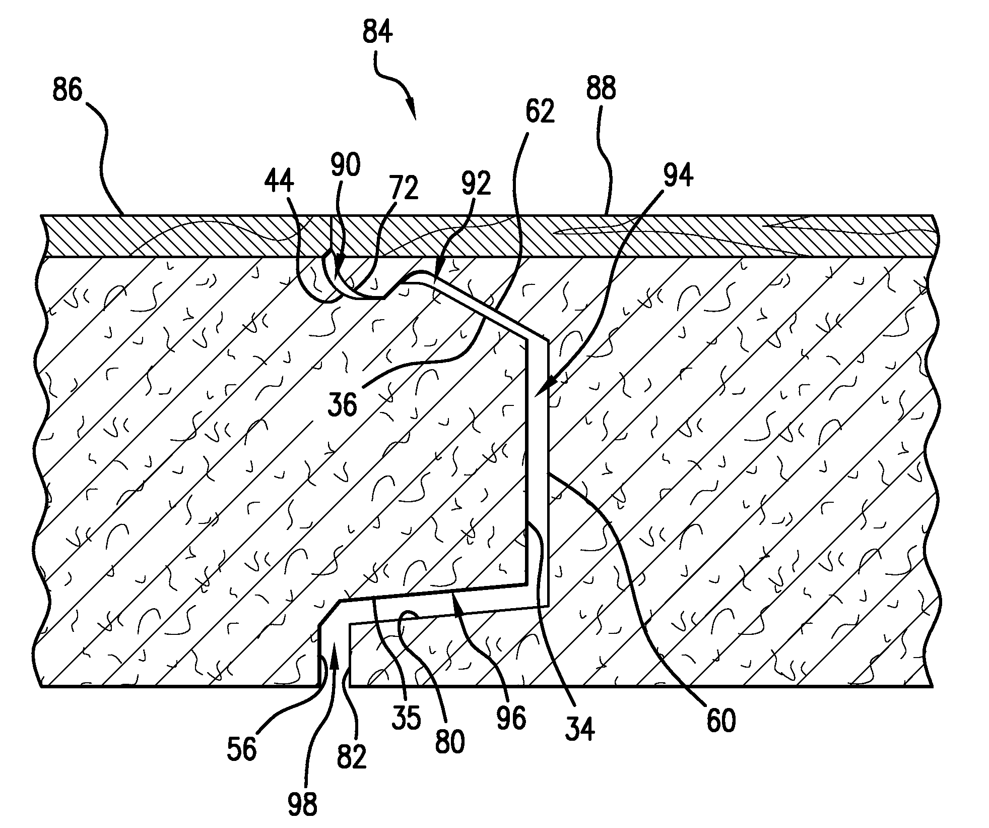
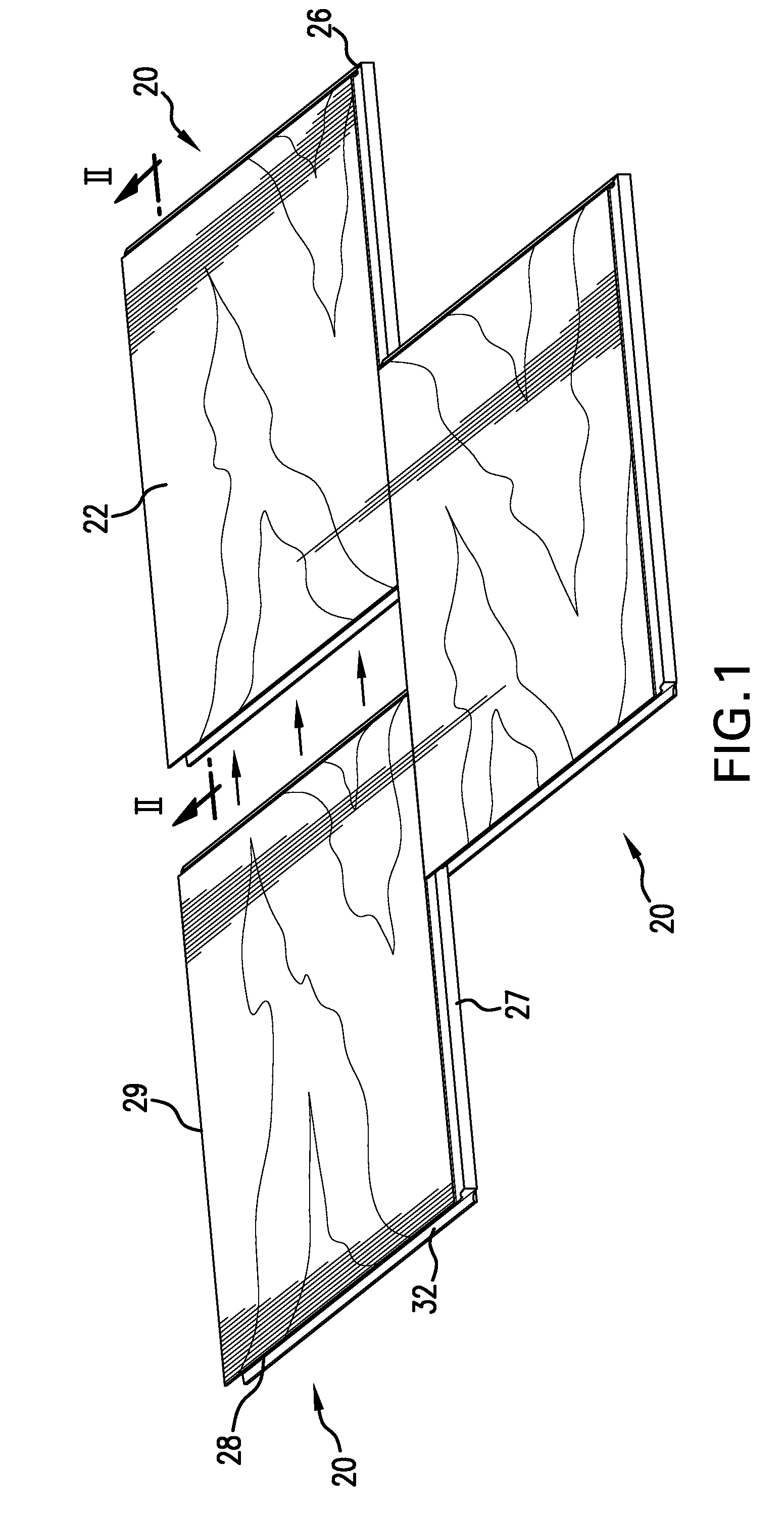
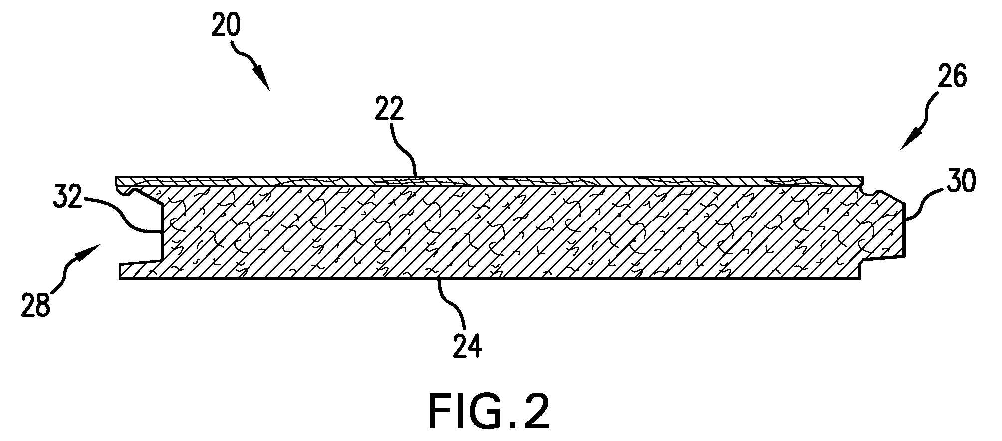
[0037]According to various embodiments, the plank can comprise a generally rectangular shape, having opposing first and second ends extending along the width of the plank, opposing first and second longitudinal sides extending along the length of the plank, and opposing top and bottom surfaces. In some embodiments, the plank comprises a tongue edge at a first end of the floor plank and a groove edge at an opposing second end of the floor plank. The tongue edge can be defined, at least partially, by a vertical distal surface that is substantially vertical with respect to the top and bottom surfaces, and a top planar slanted surface extending away from the vertical distal surface toward the top surface of the plank. A vertical lip can be included that extends downwardly from the top surface of the plank, and a slanted tongue bottom extending away from the vertical distal surface towards the bottom surface. A channel can be disposed substantially between the top planar slanted surface ...


PUM


Abstract

A plank is provided that has opposing first and second ends extending along a width of the plank, opposing first and second longitudinal sides extending along a length of the plank, and opposing top and bottom surfaces. The plank can have a tongue edge at the first end and a groove edge at the second end. The tongue edge can be detachably lockable into the groove edge of an adjacent, identical plank. Surface covering systems having a plurality of the planks connected together are also provided.

Description

BACKGROUND OF THE INVENTION[0001]This application claims the benefit under 35 U.S.C. §119(e) of prior U.S. Provisional Patent Application No. 61 / 033,979, filed Mar. 5, 2008, which is incorporated in its entirety by reference herein.[0002]The present invention relates to surface-coverings, like flooring, and methods of installing the same.[0003]Various types of glueless mechanical locking systems (including straight tongue and groove arrangements) have been utilized in the flooring industry. Flooring with glueless mechanical locking systems (tongue and groove arrangements) are becoming increasingly popular, as they are easy to lay, and, thus, it is not necessary to utilize highly trained personnel to lay such floor tiles.[0004]Current floor systems have suffered, however, from disadvantages. One disadvantage experienced with current floor systems is that if each of the side edges of a plank includes a mechanical locking tongue or groove, once one of the side edges is connected to ano...

Claims


Application Information

Patent Timeline
IPC IPC(8): E04F15/16
CPCE04F13/08E04F2201/0153E04F2201/0115E04F15/02E04F15/042
Inventor CHEN, HAO A.WHISPELL, JOHN M.
Owner MANNINGTON MILLS
Why Eureka
Try Eureka