Aircraft Wing and Fuselage Structure

a fuselage structure and aircraft technology, applied in the field of structures, can solve the problems of low flying speed and short landing distance achieved by birds, huge cost of high-speed jet aircraft, and few aircra

Inactive Publication Date: 2009-09-10
WHITE WALTER W
View PDF16 Cites 12 Cited by
  • Summary
  • Abstract
  • Description
  • Claims
  • Application Information

AI Technical Summary

Benefits of technology

[0019]An object of the present invention is to use a thin, light weight, metal or composite material formed in a shape that given the forces acting upon it will cause a substantial portion of the structure in compression to be protected from premature buckling and failure of the thin material.
[0042]For high wing monoplanes, with two seat wide fuselages, the upper and lower compound curve hyper camber fuselage elements can be quite shallow vertically, with enough vertical space left between them to provide side access for both passengers and cargo and provide headroom. The upper and lower elements would be deflected toward each other and held together in the same manner described above. The wing would go over the top of the fuselage and means would be provided to connect it securely to the fuselage.

Problems solved by technology

Yet, few aircraft, outside of certain ultra lights using wings concave underneath can approach the low flying speeds and short landing distances achieved by birds.
While the enormously large and fast fixed wing aircraft of today have created a travel industry unheard of in the 19th century, and specialized military aircraft have achieved a capability of delivering weaponry of unparallel magnitude and weight at world spanning distances, their remains a niche, unfilled by present powered fixed wing aircraft, for a fixed wing aircraft which can land and take off within extremely short distances.
Today, high speed jet aircraft are enormously expensive to build, because of their complicated structure, consume enormous amounts of jet fuel, and except for a few advanced drones, are completely inadequate to provide very low altitude tactical support to military forces or civilian police actions.
In like manner, surveillance of terrorist activities, border crossing problems or covert criminal activities go largely unseen by piloted fixed wing aircraft which are either too fast, too big, too expensive, or lack maneuverability capabilities.
In short, our present fixed wing aircraft are largely unsuitable for a substantial number of necessary activities.
Furthermore, our reconnaissance aircraft are too large, consume too much fuel, and are too expensive to be used in risky low level slow speed surveillance where they might be brought down by any number of weaponry within the means of those under surveillance.

Method used


Image

  • Aircraft Wing and Fuselage Structure
  • Aircraft Wing and Fuselage Structure
  • Aircraft Wing and Fuselage Structure

Examples


Embodiment Construction

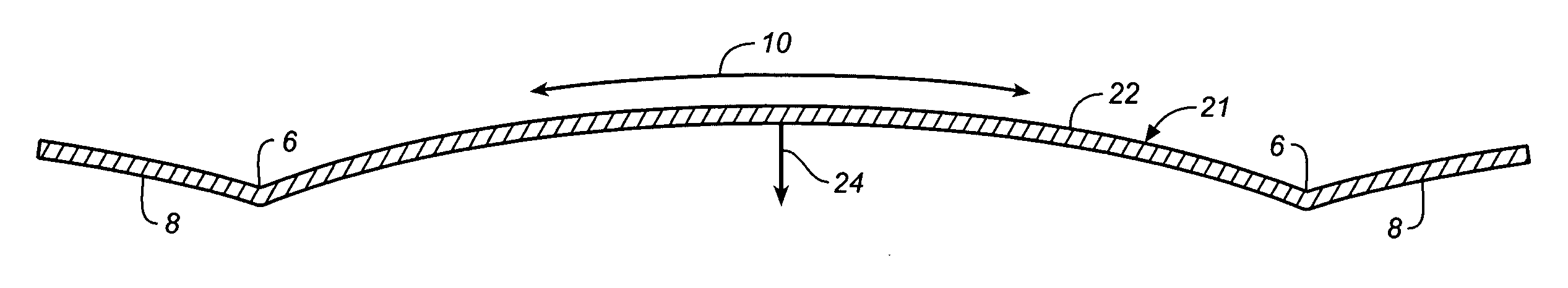
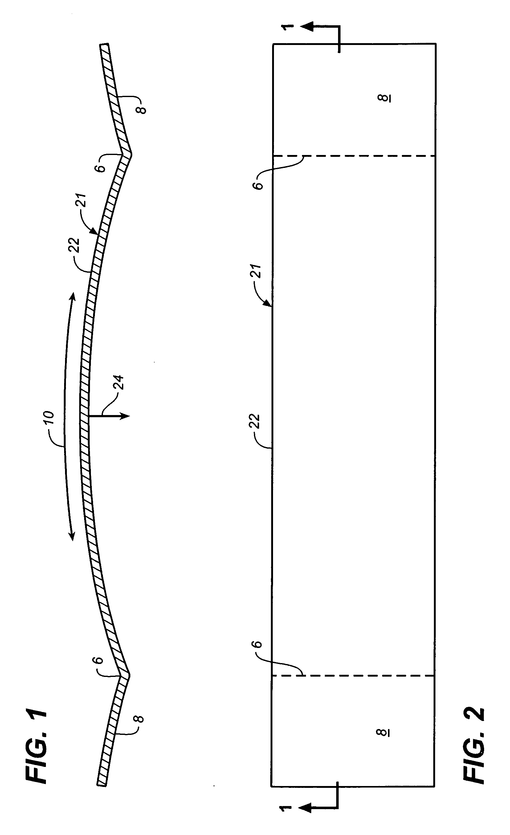
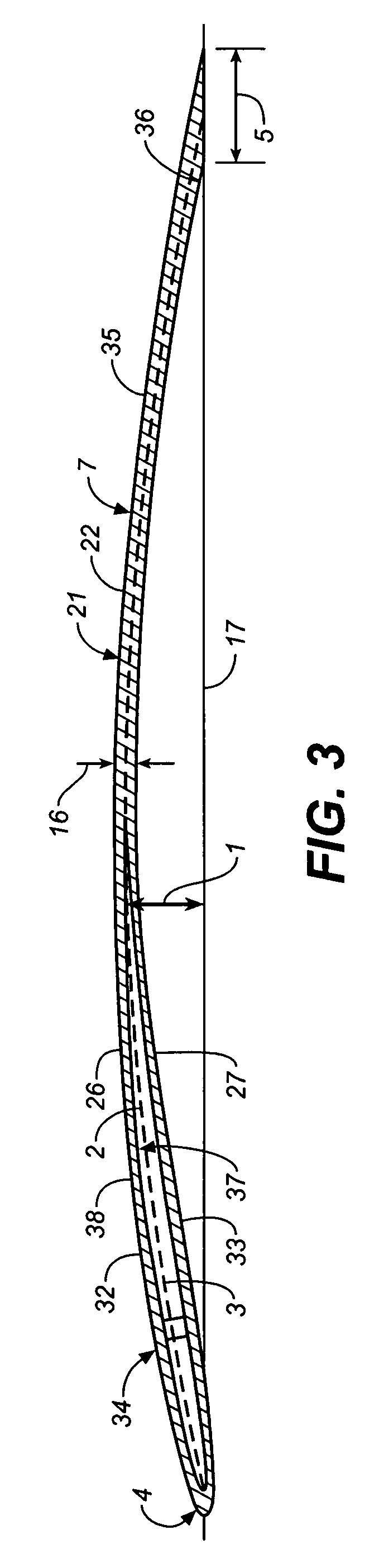
[0054]The present invention consists of a structure configured to resist bending stresses resulting from design loads; the structure being further configured so that the bending stresses produce force components which resist buckling of thin material portions of the structure stressed in compression.

[0055]The structure is of relatively thin sheet material and curved laterally throughout a substantial portion of its length, to an overall selected depth sufficient to provide the necessary strength to resist maximum design bending stress. The structure also has a longitudinally cambered shape that is initially curved opposite to the bend that occurs when the structure is loaded, and has an initial cambered magnitude sufficient so that positive residual camber remains under maximum design load, the longitudinally cambered configuration curvature and orientation, is selected so that, when loaded, a longitudinal compressive force exists, having force components directed away from the cent...


PUM


Abstract

A structure protected from premature buckling for resisting multiple bending forces resulting from design loads in which the resulting structural configuration is determined by the force components produced by the design bending stresses. The structure is a compound curved, relatively thin sheet of metal or a composite having a longitudinally cambered shape that is initially arched opposite to the bend that occurs when the structure is loaded and is likewise curved laterally through a substantial portion of its length. The structure is particularly suited for the construction of fixed wing airplanes and airplane fuselages using the same principles of construction. The wing structure is characterized by a concave undersurface like that of a bird's wing which results in a greatly reduced stall speed which cannot stall out at slow speeds.

Description

BACKGROUND OF THE INVENTION[0001]The present invention relates to a structure which can be used as aircraft wings as well as multiple joined structures forming the fuselage. As a wing, the structure curves in a longitudinal hyper camber or excessive camber curve and also curves laterally leading edge to trailing edge forming a compound curve. In the fuselage, the multiple structures curve from nose to tail in a longitudinal hyper camber curve and also curve laterally forming a compound curve.[0002]The present invention relates to a hyper camber aircraft structure which astoundingly can be used as the entire structural member of an aircraft wing as well as the main structural members of the fuselage. The history of winged aircraft dates back to the late 19th century with glider craft such as the well known Lilienthal flying machine which received U.S. Pat. No. 544,816 on Aug. 20, 1895. As Lilienthal stated in his patent: “This invention relates to flying-machines which resemble in th...

Claims


Application Information

Patent Timeline
Patent Type & Authority Applications(United States)
IPC IPC(8): B64C1/00E04B1/32B64C3/00
CPCB64C1/068B64C1/12B64C3/26B64C3/16B64C3/14
Inventor WHITE, WALTER W.
Owner WHITE WALTER W
Why Eureka
Try Eureka