Vehicle stabilizer system

a technology of stabilizer system and vehicle, which is applied in the direction of cycle equipment, transportation and packaging, instruments, etc., can solve the problems of deteriorating vehicle stability and vehicle ride comfort, and achieve good vehicle stability, ride comfort and so on, and high utility of the system

Inactive Publication Date: 2009-09-10
TOYOTA JIDOSHA KK
View PDF2 Cites 27 Cited by
  • Summary
  • Abstract
  • Description
  • Claims
  • Application Information

AI Technical Summary

Benefits of technology

[0004]In the light of the structure of the stabilizer system mentioned above, delay in the operation of the actuator, external input force other than the above-indicated external input force arising from the roll moment due to the turning of the vehicle (e.g., disturbance external input force due to roughness or bumpiness of a road surface) are factors that deteriorate the vehicle stability, the vehicle ride comfort and the like. Accordingly, the active stabilizer system has enhanced utility by appropriately dealing with those factors. While the description made just above is one aspect relating to the stabilizer system, active stabilizers under development can be modified in various aspects and have much room for improvement to enhance the utility. The present invention has been made in the light of the above. It is therefore an object of the invention to improve the utility of the vehicle stabilizer system.
[0108]The above-indicated form (48) is a form in which the change pattern of the electrified phase of the motor in the phase-change-executing no-power-supply mode is selected on the basis of the operational direction of the actuator with respect to the neutral position. According to this form, when the actuator is operated in the neutral direction by the external input force, the resistance against the operation in the neutral direction can be made small. On the other hand, when the actuator is operated in the counter-neutral direction, the resistance against the operation in the counter-neutral direction can be made large. Therefore, the present mode satisfies both of the easiness of return to the neutral position and the stability of the vehicle body when the roll moment acts thereon.

Problems solved by technology

In the light of the structure of the stabilizer system mentioned above, delay in the operation of the actuator, external input force other than the above-indicated external input force arising from the roll moment due to the turning of the vehicle (e.g., disturbance external input force due to roughness or bumpiness of a road surface) are factors that deteriorate the vehicle stability, the vehicle ride comfort and the like.

Method used


Image

  • Vehicle stabilizer system
  • Vehicle stabilizer system
  • Vehicle stabilizer system

Examples


Embodiment Construction

[0145]There will be described in detail one embodiment of the claimable invention, referring to the drawings. It is to be understood, however, that the invention is not limited to the following embodiment but may be embodied with various changes and modifications, such as those described in the FORMS OF THE INVENTION, which may occur to those skilled in the art.

1. Structure of Stabilizer System

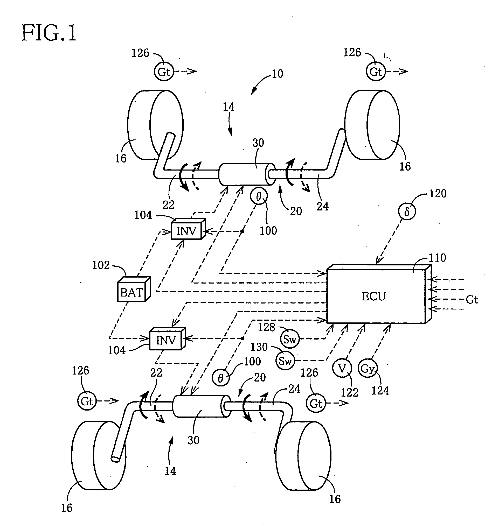
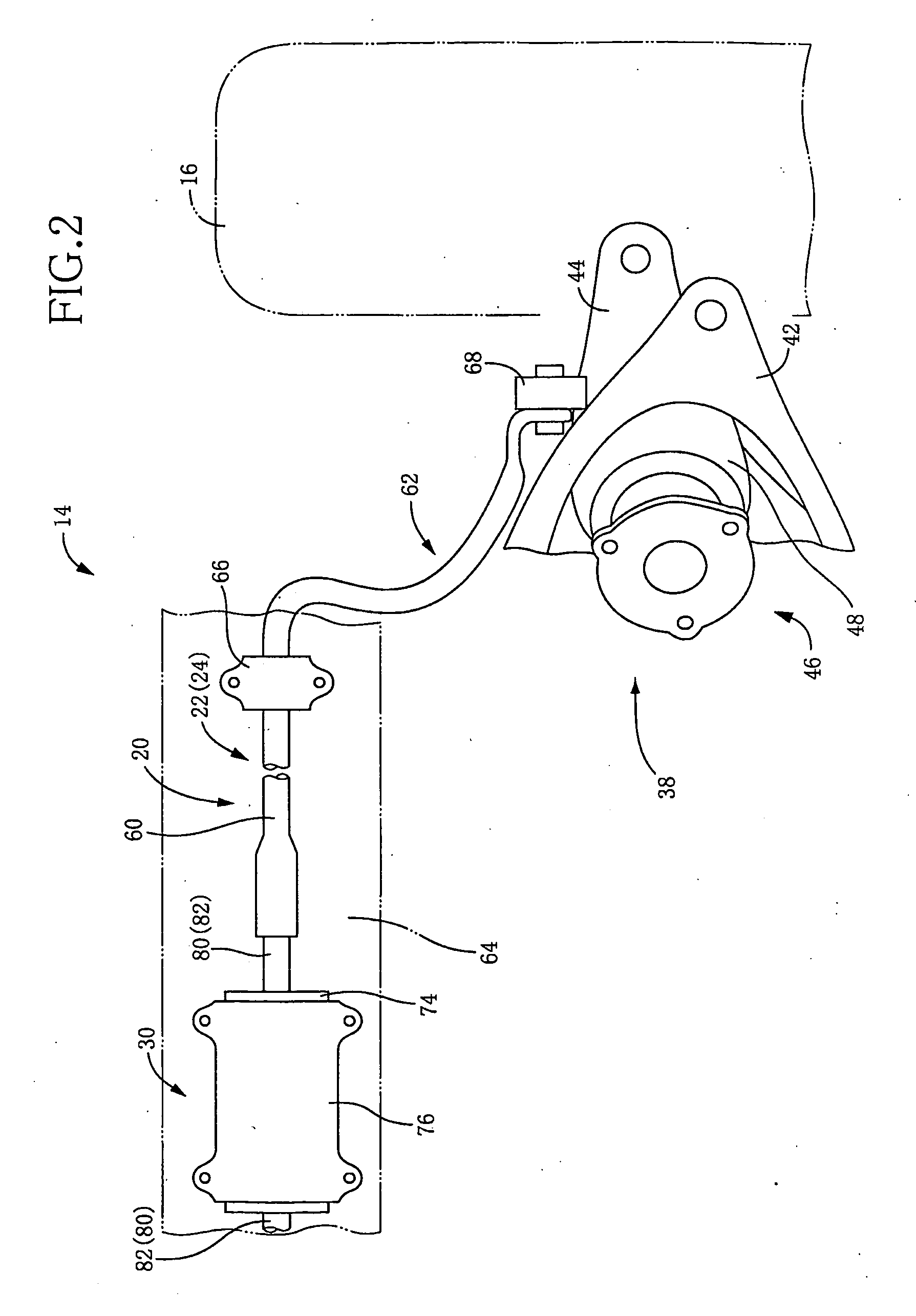
[0146]FIG. 1 conceptually shows a stabilizer system 10 for a vehicle according to one embodiment of the claimable invention. The stabilizer system 10 includes two stabilizer apparatuses 14 which are disposed respectively on a front-wheel side and a rear-wheel side of the vehicle. Each stabilizer apparatus 14 includes a stabilizer bar 20 connected at opposite ends thereof to respective wheel holding members (FIG. 2) which respectively hold right and left wheels 16. The stabilizer bar 20 is divided at a middle portion thereof into two parts, i.e., a right stabilizer bar member 22 and a left stab...


PUM


Abstract

A stabilizer system for a vehicle includes a stabilizer bar and an actuator and that executes a control actively changing stiffness of the stabilizer bar in accordance with roll moment acting on a body of the vehicle. Each of a situation in which the vehicle is running straightforward and a situation in which a torque generating direction of a motor of the actuator changes in opposite direction plural times is identified as a specific situation. In the specific situation, a control of changing an operation mode of the motor such that presence or absence of occurrence of resistance of the actuator against its operation by external input force is changeable, and a control of limiting a supply current to the motor such that the torque generating direction of the motor is inhibited from coinciding with a direction away from a neutral position are executed.

Description

TECHNICAL FIELD[0001]The present invention relates in general to a stabilizer system installed on a vehicle for reducing or restraining roll of a body of the vehicle, and more particularly to such a stabilizer system in which rigidity of a stabilizer bar is changeable by an actuator having an electric motor.BACKGROUND ART[0002]In recent years, there has been developed a so-called “active stabilizer system”, in detail, a stabilizer system in which stiffness or rigidity of a stabilizer bar is changed for thereby effectively controlling or restraining roll of a vehicle body. For instance, JP-A-2002-518245 and JP-A-2000-71738 disclose such a stabilizer system. Each of the disclosed stabilizer systems is equipped with an actuator which has an electric motor and which changes the stiffness of the stabilizer bar. By controlling the operation of the actuator, the roll of the vehicle body is effectively restrained or suppressed.DISCLOSURE OF THE INVENTION(A) Summary of the Invention[0003]The...

Claims


Application Information

Patent Timeline
Patent Type & Authority Applications(United States)
IPC IPC(8): B60G21/055
CPCB60G17/0162B60G2800/9122B60G21/0556B60G2202/135B60G2202/42B60G2204/4191B60G2204/62B60G2400/104B60G2400/204B60G2400/412B60G2500/20B60G2600/187B60G2800/012B60G2800/24B60G21/0555
Inventor BUMA, SHUUICHICHO, JAESUNG
Owner TOYOTA JIDOSHA KK
Why Eureka
Try Eureka