Energy conserving (stand-by mode) power saving design for battery chargers and power supplies

a technology of power supply and battery charger, applied in the field of electronic systems, can solve problems such as power consumption

Active Publication Date: 2009-09-10
CHEMTRON RES
View PDF5 Cites 50 Cited by
  • Summary
  • Abstract
  • Description
  • Claims
  • Application Information

AI Technical Summary

Benefits of technology

[0007]It is an aspect of the embodiments dis...

Problems solved by technology

These devices typically operate in t...

Method used


Image

  • Energy conserving (stand-by mode) power saving design for battery chargers and power supplies
  • Energy conserving (stand-by mode) power saving design for battery chargers and power supplies
  • Energy conserving (stand-by mode) power saving design for battery chargers and power supplies

Examples


first embodiment

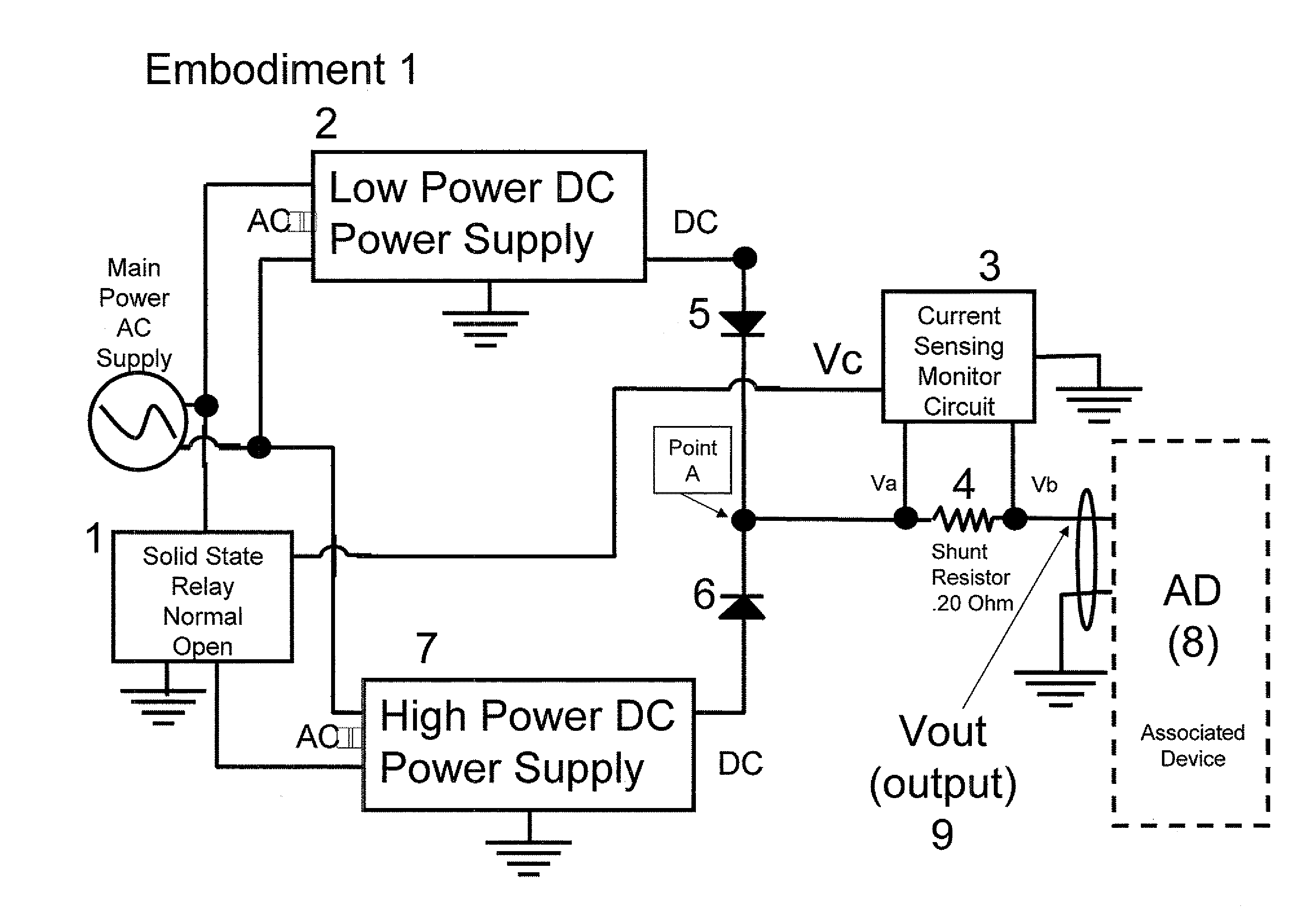
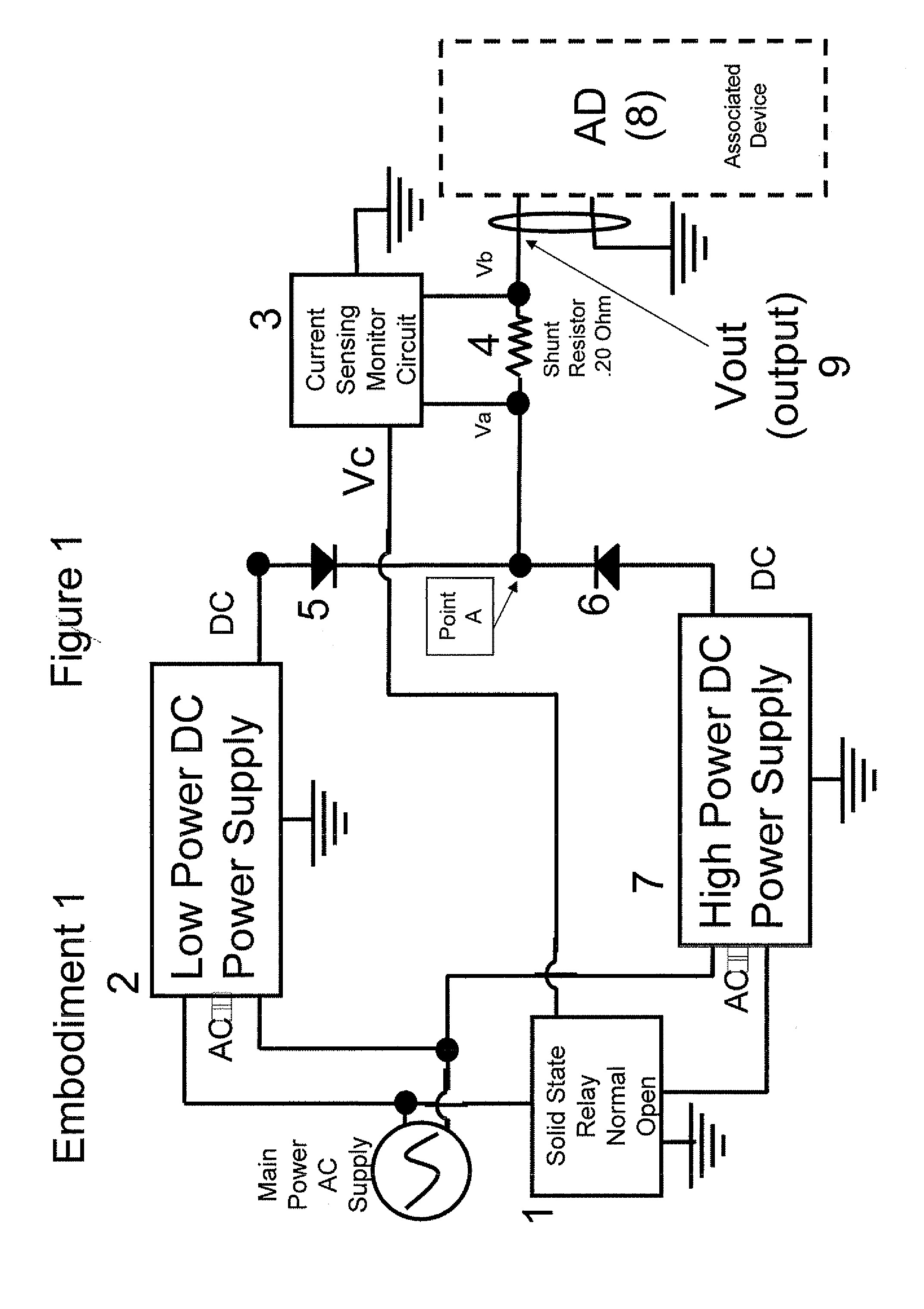
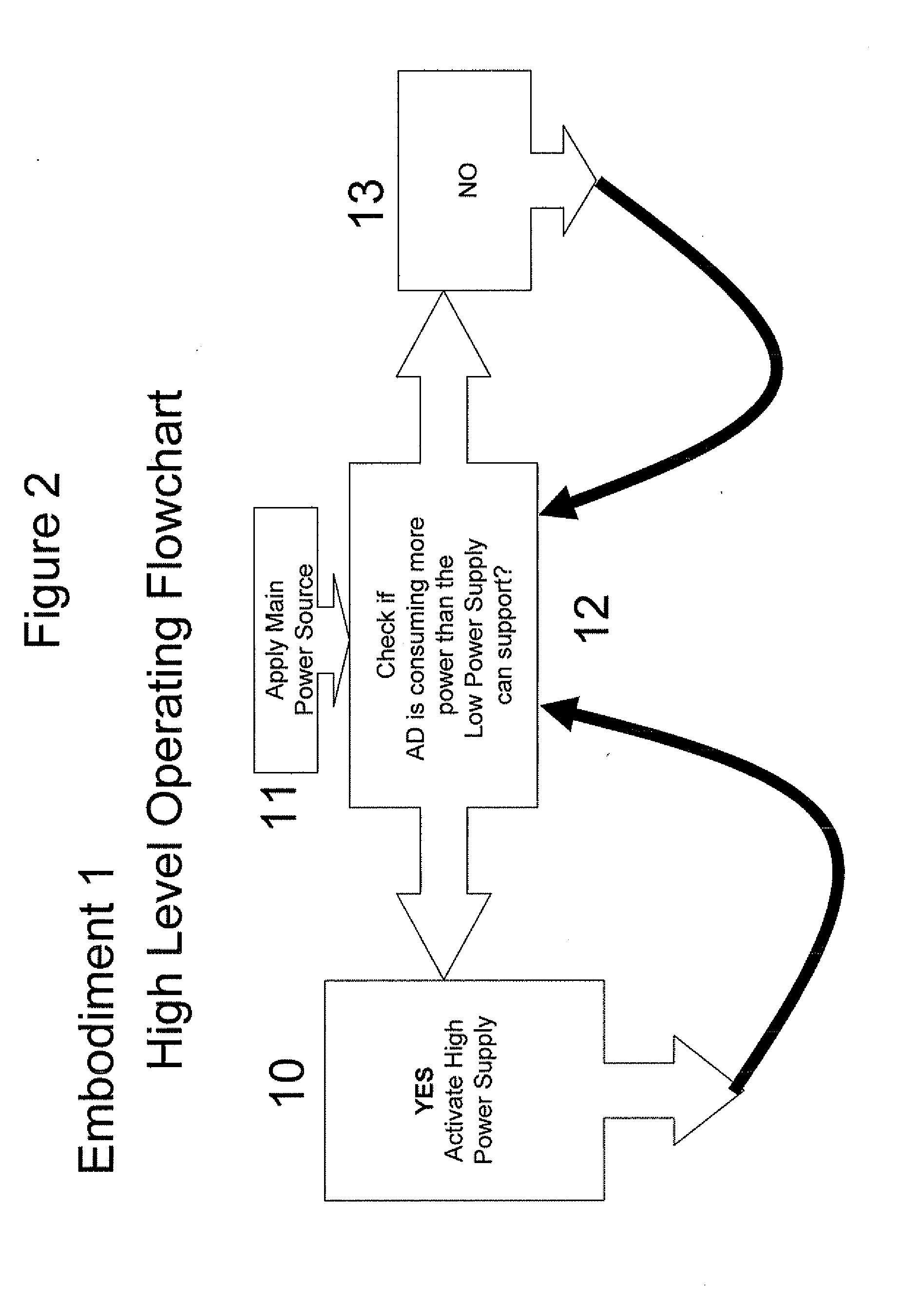
[0017]The following embodiment, as depicted in FIG. 1, is of a power supply and / or battery charger (PS / BC) system used to power associated devices (8) (AD (8)) with power consumption characteristics that include low power consumption (50% to 99% of the time) and high power consumption (1%-50% of the time). The first embodiment operating flow charts are depicted in FIGS. 2 and 3. This embodiment is a design to power a rechargeable laptop computer. The exact ratio of time the AD (8) requires high power versus low power is not critical.

[0018]The embodiment discussed herein includes a power supply or battery charger (PS / BC) designed to minimize the power consumption of itself during the times the AD (8) is disconnected, in stand-by, sleep mode or off. FIG. 1 shows a power supply or battery charger (PS / BC) in accordance with this embodiment.

[0019]The embodiment switches between a low power (LPM) and high power mode (HPM) depending on the real time power consumption requirements of the AD...


PUM


Abstract

A system is described that turns off a high power, power supply when a device no longer needs high power. A low power, power supply or a rechargeable battery provides power to determine when the device again needs high power. The low power supply consumes a minimum possible power when the device does not need high power and the power rechargeable battery is not charged. That is, the high power and low power, power supplies are turned on or off based on the real time power consumption of the device and the charged state of the battery. The power need of the device is monitored by a current shunt monitoring circuit.

Description

CROSS-REFERENCE TO RELATED APPLICATION[0001]This application is related to and claims priority to U.S. provisional application entitled Energy Conserving (Stand-by Mode) Power Saving Design for Battery Chargers and Power Supplies having Ser. No. 61 / 034,782, by Perper, filed Mar. 7, 2008 and incorporated by reference herein.BACKGROUND[0002]1. Field[0003]The embodiments discussed herein are directed to electronic systems, and more specifically to the power supplies in electronic systems.[0004]2. Description of the Related Art[0005]The electronics industry has developed power supply (PS) and battery charger (BC) systems to power associated devices (AD) including portable DVD players, laptops, video games and televisions to home appliances. Many of these devices have an in-use or full power cycle ratio 1% to 50%. The power cycle indicates the percentage of time that the AD requires the full power potential of the power supply. These devices typically operate in two modes, low and high, ...

Claims


Application Information

Patent Timeline
IPC IPC(8): H02J1/10
CPCG06F1/26G06F1/3212H02J1/108Y02B60/1292H02J9/005H02J1/00H02J7/02Y02D10/00Y04S20/20Y02B70/30H02J5/00H02J7/00H02J3/00
Inventor PERPER, HARRY LEONARDBECKERS, JAMES RANDALL
Owner CHEMTRON RES
Why Eureka
Try Eureka