
Illumination Device, In Particular for Microscopes

a technology of illumination device and microscope, which is applied in the direction of discharge tube luminescnet screen, electric variable regulation, instruments, etc., can solve the problems of limited intensity, limited size of second light source, and large resources required for this purpos

Inactive Publication Date: 2009-09-10
CARL ZEISS MICROSCOPY GMBH
View PDF13 Cites 15 Cited by
  • Summary
  • Abstract
  • Description
  • Claims
  • Application Information

AI Technical Summary

Benefits of technology

[0013]It is the primary object of the present invention to provide an illumination device which is electronically switchable, can be regulated with respect to brightness, emits different colors selectively or emits the color white additively with all of the components of white light and which is homogeneous over the illuminated field. The intensity is high enough so that all essential contrasting methods in microscopy are possible with the illumination device.

Problems solved by technology

While all contrasting methods in microscopy can be realized by means of these light sources, the resources required for this purpose are usually considerable.
The disadvantage in the LED-based RGB illumination for microscopy according to the prior art consists in that the spectral distribution does not cover the entire visual area which is necessary for the color-correct representation of microscopic samples.
This solution has the drawback that the second light source is limited in size and therefore in intensity.

Method used


Image

  • Illumination Device, In Particular for Microscopes
  • Illumination Device, In Particular for Microscopes
  • Illumination Device, In Particular for Microscopes

Examples


Embodiment Construction

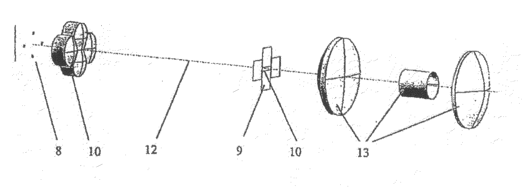
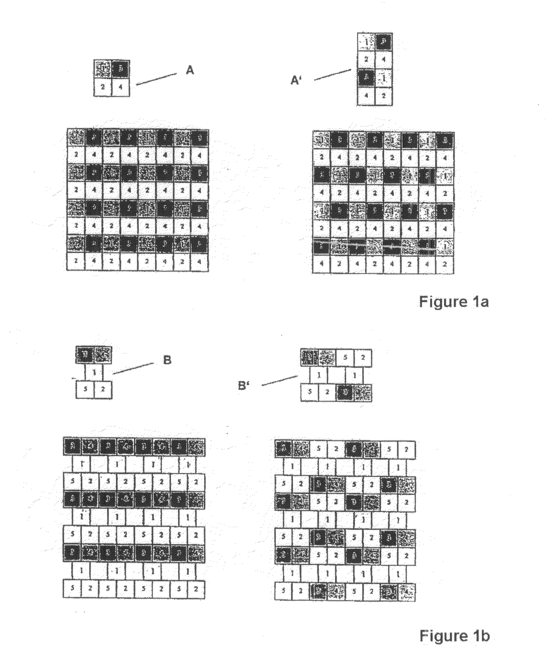
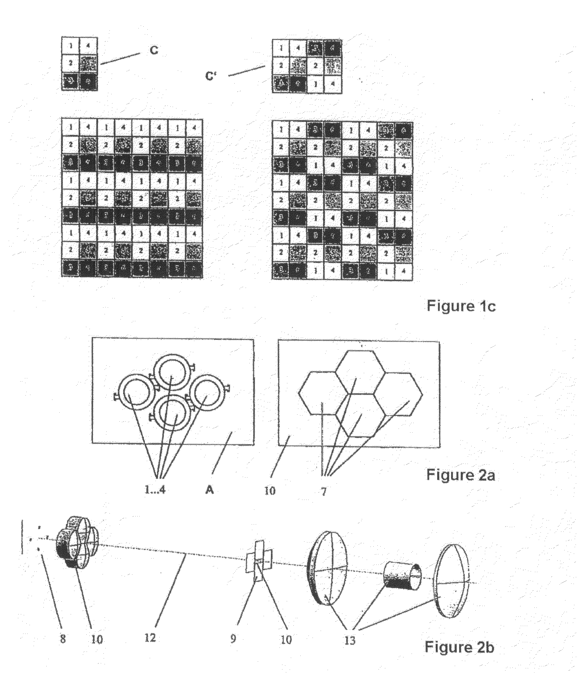
[0026]The illumination device according to the invention, particularly for microscopes, comprises a plurality of individual light sources which can be regulated with respect to brightness. These individual light sources are formed as unit cells and form a luminous surface by means of a periodic arrangement.

[0027]The luminous surface formed by the individual light sources can be planar, can have a conical section shape or a convex or concave shape. The carrier surface receiving the individual light sources is preferably reflecting.

[0028]The unit cell defines the smallest, at least 2-dimensional arrangement of light sources from which an at least two-dimensional surface can be filled by means of a periodic arrangement. The unit cells comprise a compact arrangement of more than three, preferably four to six, individual light sources with at least two different colors. In specific cases, individual light sources of the same color can also be used. In order to prevent color inhomogeneiti...


PUM


Abstract

The present invention is directed to a controllable microscope illumination within a microscope system by which all essential contrasting methods in microscopy can be realized. The illumination device according to the invention comprises a plurality of individual light sources which can be regulated with respect to brightness, wherein these individual light sources are formed as unit cells and form a luminous surface by a periodic arrangement. In an advantageous arrangement, imaging optics are associated with each individual light source in order to magnify the image of the source surface of the individual light source so that the images of the source surfaces of adjacent individual light sources touch. Illumination variants for all of the essential contrasting methods in microscopy can be generated by means of the proposed solution. The proposed LED illumination is electronically switchable, can be regulated with respect to brightness, supplies all colors, is long-lasting and economical. LEDs have a long life and are very robust and insensitive to vibrations. The spatial light distribution and the color temperature are adjustable.

Description

CROSS-REFERENCE TO RELATED APPLICATIONS[0001]This application claims priority of International Application No. PCT / EP2006 / 006001, filed Jun. 22, 2006 and German Application No. 10 2005 029 119.8, filed Jun. 23, 2005, the complete disclosures of which are hereby incorporated by reference.BACKGROUND OF THE INVENTION[0002]a) Field of the Invention[0003]The present invention is directed to a controllable microscope illumination within a microscope system by which all essential contrasting methods in microscopy can be realized.[0004]b) Description of the Related Art[0005]High-pressure lamps and halogen lamps are conventionally used in the prior art as microscope illumination. Because of deficient controllability with respect to brightness, color temperature and / or color, additional optical components such as filters, attenuators, and so on, are needed for controlling the output signal of the light source. Another essential feature is the given geometry of the light sources that are used ...

Claims


Application Information

Patent Timeline
Patent Type & Authority Applications(United States)
IPC IPC(8): H05B37/02H01J1/63
CPCG02B21/06
Inventor HORING, LUTZNOLTE, ANDREASBREHM, MICHAELSONDERMANN, MARIO
Owner CARL ZEISS MICROSCOPY GMBH
Learn More