
High speed preamplifier circuit, detection electronics, and radiation detection systems therefrom

a preamplifier circuit and high-speed technology, applied in amplifiers, amplifiers with semiconductor devices only, amplifiers, etc., can solve the problems of not being able to use sensors in general use, and placing detector electronics in vacuum is not compatible with conventional preamplifying circuitry

Active Publication Date: 2009-09-10
UT BATTELLE LLC
View PDF3 Cites 8 Cited by
  • Summary
  • Abstract
  • Description
  • Claims
  • Application Information

AI Technical Summary

Problems solved by technology

However, placing the detector electronics in the vacuum is not compatible with conventional preamplification circuitry due mainly to large amounts of power dissipation.
Additionally, other on board support circuitry useful in such environments for example temperature sensors are not in generally used.

Method used


Image

  • High speed preamplifier circuit, detection electronics, and radiation detection systems therefrom
  • High speed preamplifier circuit, detection electronics, and radiation detection systems therefrom
  • High speed preamplifier circuit, detection electronics, and radiation detection systems therefrom

Examples


Embodiment Construction

[0029]The invention describes a preamplifier circuit for processing a signal provided by a radiation detector, detector electronics including preamplifiers according to the invention, and related radiation detection systems. The preamplifier circuit comprises a transimpedance amplifier coupled to receive a current signal from a detector which outputs a low current, such as a linear position detector, and generate a voltage signal at its output. A second amplification stage has an input coupled to an output of the transimpedance amplifier for amplifying the voltage signal. Significantly, unlike conventional state of the art preamplifier circuitry, the first stage transimpedance amplifier does not integrate detected charge and the second amplification stage does not provide pulse shaping.

[0030]The second amplification stage generally comprises a second op amp and preferably includes structure for compensating voltage or current offsets coupled to a non-inverting input of the second op...


PUM


Abstract

A preamplifier circuit for processing a signal provided by a radiation detector includes a transimpedance amplifier coupled to receive a current signal from a detector and generate a voltage signal at its output. A second amplification stage has an input coupled to an output of the transimpedance amplifier for providing an amplified voltage signal. Detector electronics include a preamplifier circuit having a first and second transimpedance amplifier coupled to receive a current signal from a first and second location on a detector, respectively, and generate a first and second voltage signal at respective outputs. A second amplification stage has an input coupled to an output of the transimpedance amplifiers for amplifying the first and said second voltage signals to provide first and second amplified voltage signals. A differential output stage is coupled to the second amplification stage for receiving the first and second amplified voltage signals and providing a pair of outputs from each of the first and second amplified voltage signals. Read out circuitry has an input coupled to receive both of the pair of outputs, the read out circuitry having structure for processing each of the pair of outputs, and providing a single digital output having a time-stamp therefrom.

Description

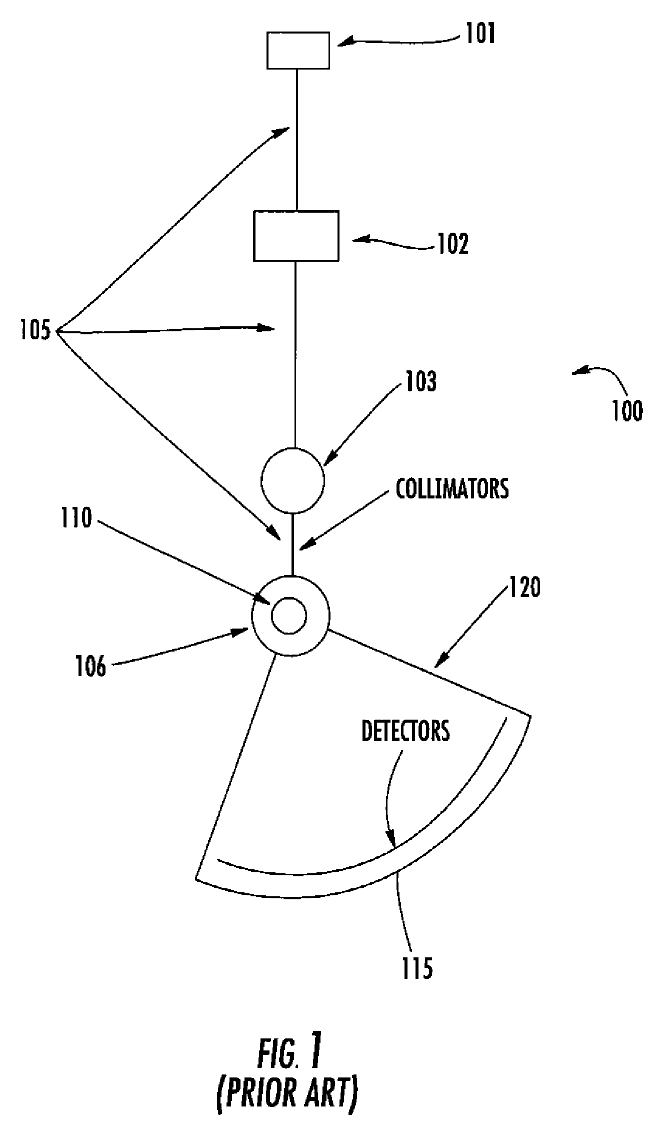
STATEMENT REGARDING FEDERALLY SPONSORED RESEARCH OR DEVELOPMENT[0001]The United States Government has rights in this invention pursuant to contract no. DEAC05-00OR22725 between the United States Department of Energy and UT-Battelle, LLC.CROSS REFERENCE TO RELATED APPLICATIONS[0002]N / AFIELD OF THE INVENTION[0003]The present invention relates to high speed preamplifier circuits, and related detector electronics and radiation detection systems.BACKGROUND OF THE INVENTION[0004]The wide angular range chopper spectrometer (ARCS) is a neutron scattering instrument being developed for the Spallation Neutron Source (SNS). ARCS provides a high neutron flux at the sample, and a large solid angle of detector.[0005]Neutrons at the SNS are produced by the spallation process where high energy protons impact a target producing a large flux of neutrons at many energies in a short period of time. The SNS instruments use time-of-flight (TOF) measurements to determine the energies of the neutrons. To d...

Claims


Application Information

Patent Timeline
Patent Type & Authority Applications(United States)
IPC IPC(8): H03F3/00
CPCH03F3/08
Inventor RIEDEL, RICHARD A.WINTENBERG, ALAN L.CLONTS, LLOYD G.COOPER, RONALD G.
Owner UT BATTELLE LLC
Learn More