Compound-eye imaging device

a compound eye and imaging technology, applied in the field of compound eye imaging devices, can solve the problems of significant reduction of such probability, inability to achieve sufficient inability to achieve significant improvement so as to achieve the effect of easy increase of the definition of the reconstructed imag

Inactive Publication Date: 2009-09-10
FUNAI ELECTRIC CO LTD
View PDF6 Cites 251 Cited by
  • Summary
  • Abstract
  • Description
  • Claims
  • Application Information

AI Technical Summary

Benefits of technology

[0015]An object of the present invention is to provide a compound-eye imaging device which substantially prevents unit images formed by respective imaging units from being the same, making it possible to easily increase the definition of a reconstructed image.
[0016]According to the present invention, this object is achieved by a compound-eye imaging device comprising: multiple imaging units having optical lenses and a solid-state imaging element with a major surface for allowing the solid-state imaging element to image multiple unit images of a target object that are formed through the optical lenses; and reconstructed image forming means for forming a reconstructed image from the multiple unit images respectively imaged by the multiple imaging units, wherein the multiple imaging units are integrally arranged, and wherein the multiple imaging units have randomly different optical imaging conditions from each other to allow the multiple unit images imaged by the multiple imaging units to be different from each other when the target object is indefinitely far.
[0017]In the compound-eye imaging device of the present invention, the multiple imaging units have randomly different optical imaging conditions, so that it substantially prevents unit images formed by the respective imaging units from being the same, making it possible to easily increase the definition of a reconstructed image.

Problems solved by technology

However, this is not possible in the case of the compound-eye imaging device 100 with regularly arranged optical lenses (L11, L12 .
However, such compound-eye imaging device does not sufficiently improve the definition of a reconstructed image.
However, the regularity in the arrangement of the optical lenses prevents a significant reduction of such probability.

Method used


Image

  • Compound-eye imaging device
  • Compound-eye imaging device
  • Compound-eye imaging device

Examples


first embodiment

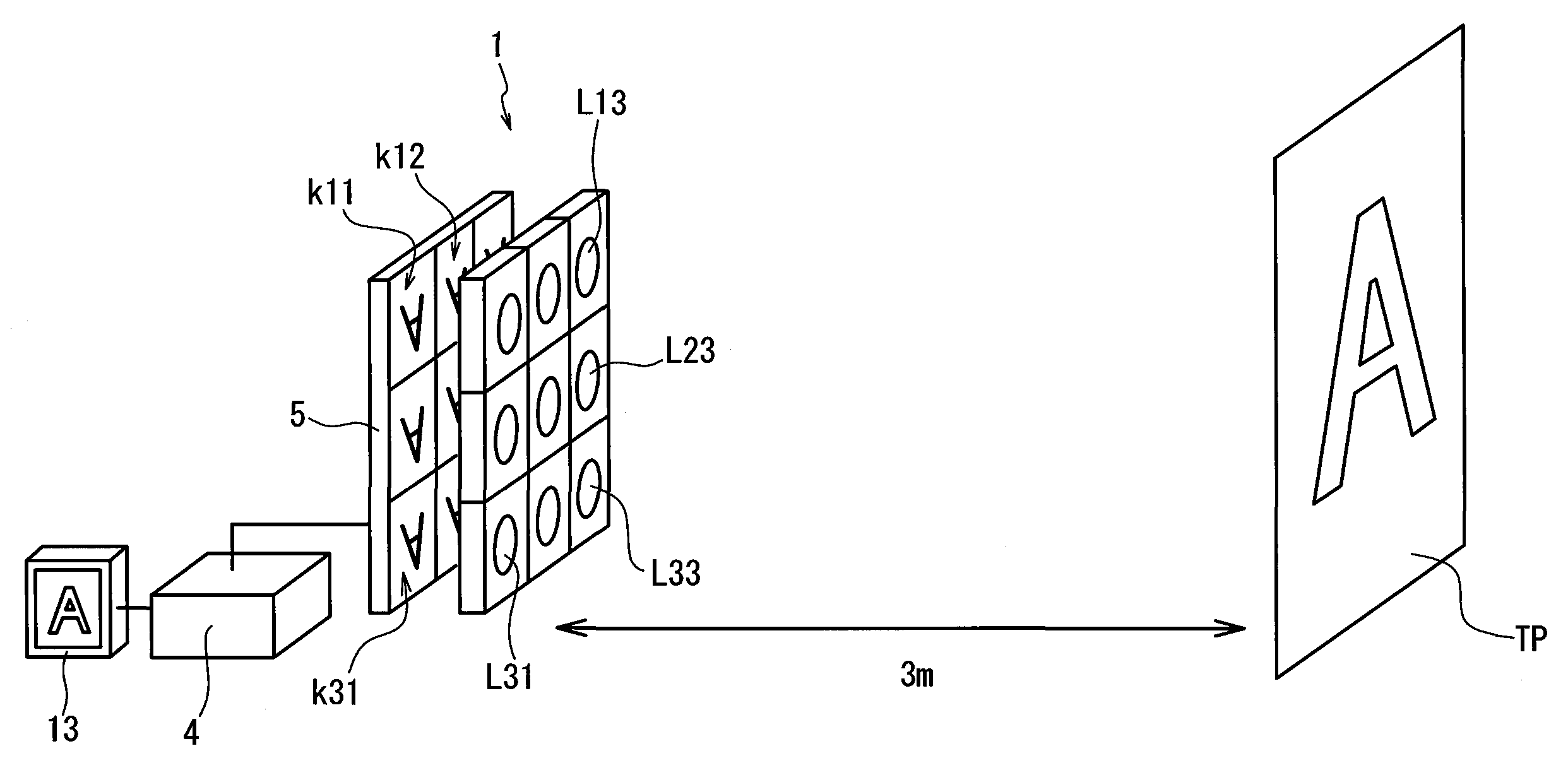
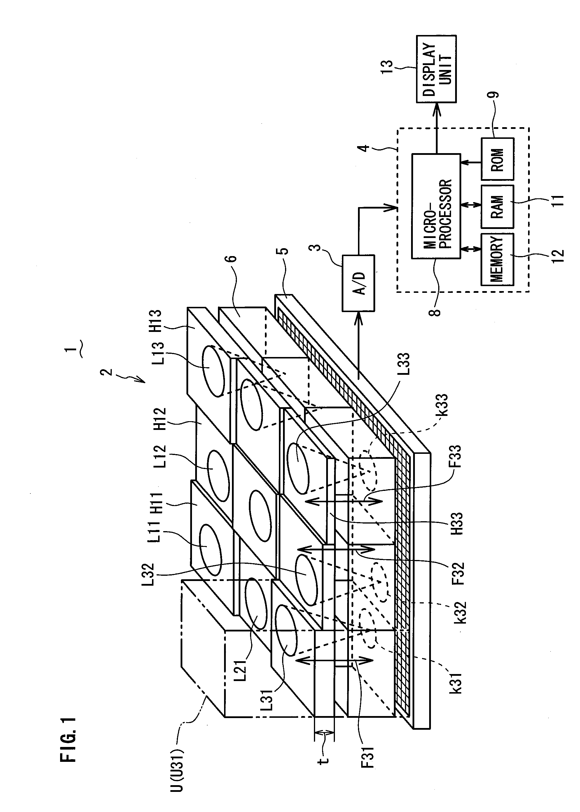
[0036]A compound-eye imaging device 1 according to a first embodiment of the present invention will be described with reference to FIG. 1 to FIG. 6. FIG. 1 is a schematic perspective view, with a block diagram, of the compound-eye imaging device 1 according to the first embodiment. As shown in FIG. 1, the compound-eye imaging device 1 comprises an imaging device body 2 for collecting light from a target object and forming an image therefrom, and an image processing unit 4 connected to the imaging device body 2 via an AD (Analog-to-Digital) converter 3 for forming a reconstructed image from image information (multiple unit images) output from the imaging device body 2.

[0037]The imaging device body 2 comprises: 9 (nine) optical lenses L11, L12 . . . L33 for collecting light from the target object; holders H11, H12 . . . H33 for holding the respective optical lenses L11, L12 . . . L33; a plate-shaped solid-state imaging element (photodetector array) 5 for imaging unit images k11, k12 ....

second embodiment

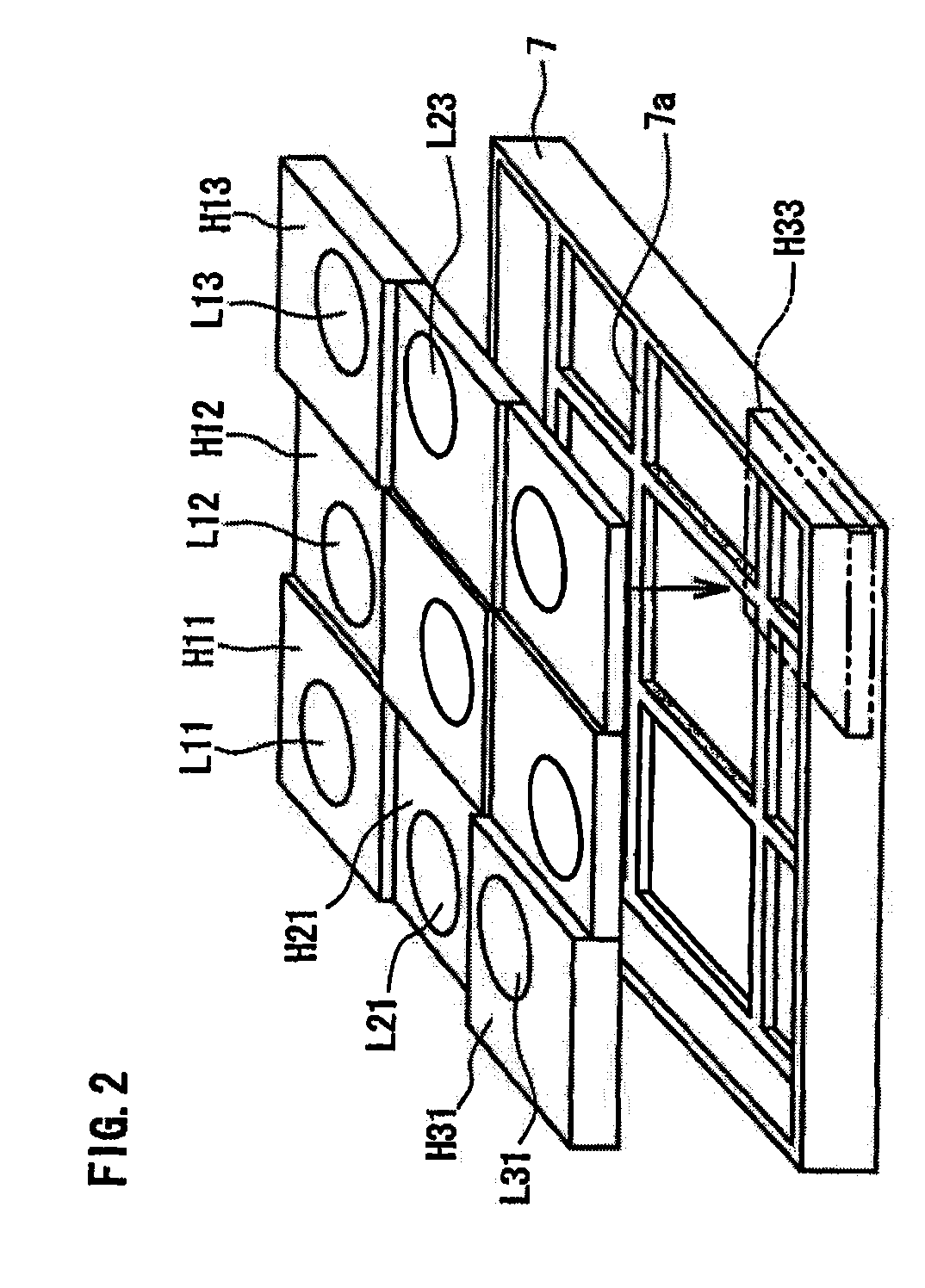
[0050]Referring now to FIG. 7, a compound-eye imaging device 1 according to a second embodiment of the present invention will be described. FIG. 7 is a schematic cross-sectional view of optical lenses L31, L32 and L33 and holders H31, H32 and H33 as a part of the compound-eye imaging device 1 of the present embodiment. The compound-eye imaging device 1 of the present embodiment is substantially the same as that of the first embodiment except for the following. In the compound-eye imaging device 1 of the first embodiment, the focal lengths F11, F12 . . . F33 of the optical lenses L11, L12 . . . L33 have randomly different values, and the distances d between the optical lenses L11, L12 . . . L33 are set to have randomly different values so as to allow the imaging units U to have different optical imaging conditions from each other. In contrast, in the present embodiment, the optical lenses L11, L12 . . . L33 are randomly inclined, i.e. are designed to have optical axes inclined at ran...

third embodiment

[0053]Referring now to FIG. 8, a compound-eye imaging device 1 according to a third embodiment of the present invention will be described. FIG. 8 is a schematic plan view showing a part of a solid-state imaging element 5 in the compound-eye imaging device 1. The compound-eye imaging device 1 of the present embodiment is substantially the same as that of the first embodiment except that here the focal lengths F11, F12 . . . F33 of the optical lenses L11, L12 . . . L33 are the same, and the distances d between the optical lenses L11, L12 . . . L33 are set to be the same, while the pixels g of the solid-state imaging element 5 are randomly arranged so as to allow the respective imaging units U to have different optical imaging conditions. More specifically, the pixels g of the solid-state imaging element 5 in the present embodiment are not regularly arranged in a matrix of rows and columns, but are randomly arranged as shown in FIG. 8.

[0054]Similarly as in the first embodiment, also in...


PUM


Abstract

A compound-eye imaging device comprises an imaging device body having 9 optical lenses and a solid-state imaging element for imaging unit images formed by the optical lenses. Assuming that the combination of each of the optical lenses with a corresponding divided area of the solid-state imaging element to image each of the corresponding unit images is an imaging unit, thereby forming multiple imaging units, the respective imaging units have randomly different optical imaging conditions. For example, the focal lengths of the 9 optical lenses are set to have random values in which the optical lenses are arranged to have random distances between adjacent ones thereof in a direction parallel to the major surface of the solid-state imaging element. This compound-eye imaging device substantially prevents unit images formed by respective imaging units from being the same, making it possible to easily increase the definition of a reconstructed image.

Description

BACKGROUND OF THE INVENTION[0001]1. Field of the Invention[0002]The present invention relates to a compound-eye imaging device.[0003]2. Description of the Related Art[0004]A compound-eye imaging device is known which comprises an optical lens array having multiple micro optical lenses arranged in a matrix of rows and columns, and a solid-state imaging element (photodetector array) for imaging multiple unit images of a target object which are formed by the respective optical lenses of the optical lens array so as to reconstruct the multiple unit images into a reconstructed image (refer to e.g. Japanese Laid-open Patent Publication 2001-61109). FIG. 9 is a schematic perspective view of a part of such conventional compound-eye imaging device 100.[0005]As shown in FIG. 9, the compound-eye imaging device 100 has an optical lens array 101 and a solid-state imaging element 102 as well as a partitioning wall 103 placed between the optical lens array 101 and the solid-state imaging element 1...

Claims


Application Information

Patent Timeline
Patent Type & Authority Applications(United States)
IPC IPC(8): H04N5/225G03B19/06G03B19/07G03B35/08H01L27/14H04N5/335
CPCG02B3/0056H04N5/3415H04N5/2254H04N25/41
Inventor TANIDA, JUNHORISAKI, RYOICHITOYODA, TAKASHINAKAO, YOSHIZUMIMASAKI, YASUO
Owner FUNAI ELECTRIC CO LTD
Why Eureka
Try Eureka