
Reconfigurable optical add/drop multiplexer and procedure for outputting optical signals from such multiplexer

a technology of optical add/drop multiplexer and optical signal, which is applied in the field of multifunctional and reconfigurable dense wavelength division multiplexing (dwdm) optical nodes, can solve the problems of limiting their usefulness, large power loss over the span of fiber optic cables, and significant osnr margin reduction

Active Publication Date: 2009-09-10
TELLABS OPERATIONS
View PDF39 Cites 34 Cited by
  • Summary
  • Abstract
  • Description
  • Claims
  • Application Information

AI Technical Summary

Benefits of technology

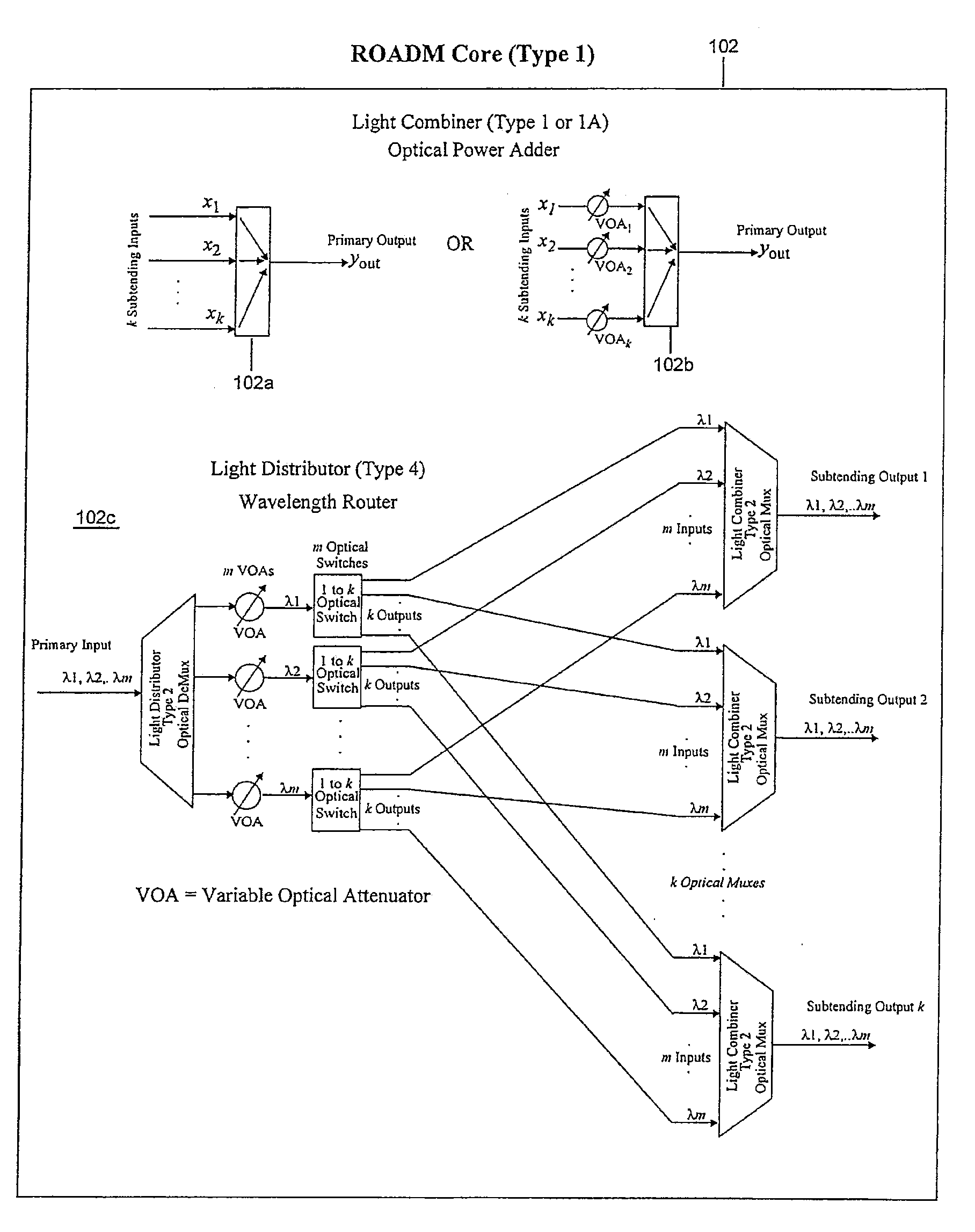
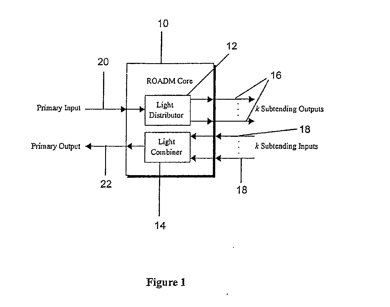
[0012]One or more of the example embodiments provide a ROADM including a plurality of local interfaces at which optical signals of different wavelengths are locally input into the ROADM, and a network interface configured to connect the ROADM to a network from which multiplexed optical signals of different wavelengths are transmitted to the network. In a first configuration, the ROADM is configured to transmit from t

Problems solved by technology

As a result, while they are reconfigurable, they are not multifunctional, which limits their usefulness.
First, the optical power of the generated cross products depletes the optical power of the optical signals transmitted on the network that carry information, and therefore FWM cross products affect channel OSNR (optical signal-to-noise ratio), resulting in a larger than normal power loss over the span of a fiber optic cable.
Second, cross products of exactly the same wavelength as optical signals carrying information on the network create coherent interference / crosstalk and produce a significant OSNR margin reduction, which can lead to traffic outages.

Method used


Image

  • Reconfigurable optical add/drop multiplexer and procedure for outputting optical signals from such multiplexer
  • Reconfigurable optical add/drop multiplexer and procedure for outputting optical signals from such multiplexer
  • Reconfigurable optical add/drop multiplexer and procedure for outputting optical signals from such multiplexer

Examples


Embodiment Construction

[0091]The example embodiments described herein meet the above-identified needs by providing procedures, apparatuses, systems and computer program products for inputting, outputting, receiving, and transmitting optical signals of multiple wavelengths. This description is not intended to limit the application of the example embodiments presented herein. In fact, after reading the following description, it will be apparent to one skilled in the relevant arts how to implement the following example embodiments in alternative embodiments (e.g., involving any apparatus or procedure for processing signals received from and / or transmitted to a network that performs the same or similar functions as the apparatus or procedures discussed below).

[0092]The example embodiments disclosed herein are discussed with respect to a DWDM environment. However, it should be understood to one ordinarily skilled in the art that the inventive techniques illustrated by the examples of the disclosed embodiments ...


PUM


Abstract

A reconfigurable optical add drop multiplexer (ROADM) includes local interfaces at which optical signals of different wavelengths are locally input into the ROADM, and a network interface configured to connect the ROADM to a network from which multiplexed optical signals of different wavelengths are transmitted to the network. In a first configuration, the ROADM is configured to transmit from the network interface to the network multiplexed signals of different wavelengths having a first minimum frequency difference. In a second configuration, the ROADM is configured to transmit from the network interface to the network multiplexed signals of different wavelengths having a second minimum frequency difference. The second minimum frequency difference is greater than the first minimum frequency difference. This arrangement reduces the power of four wave mixing cross products produced when optical signals of three wavelengths are multiplexed and transmitted from the ROADM to NZDSF or DSF fiber types.

Description

CROSS-REFERENCE TO RELATED APPLICATION[0001]This application claims the benefit of U.S. Provisional Application No. 60 / 924,732 filed May 30, 2007.INCORPORATION BY REFERENCE[0002]The present application incorporates by reference the entire contents of U.S. Provisional Application No. 60 / 924,732 filed May 30, 2007.BACKGROUND[0003]1. Field[0004]Example embodiments disclosed herein relate in general to the field of wavelength division multiplexing and more particularly to a multifunctional and reconfigurable Dense Wavelength Division Multiplexing (DWDM) optical node. Example embodiments disclosed herein also relate to an optical node and an optical network including a reconfigurable optical add drop multiplexer core device.[0005]2. Related Art[0006]Wavelength Division Multiplexing (WDM) and Dense Wavelength Division Multiplexing (DWDM) are technologies that enable a multitude of optical wavelengths of differing frequencies to be transported over a single optical fiber. A DWDM network is...

Claims


Application Information

Patent Timeline
IPC IPC(8): H04J14/02
CPCH04J14/0205H04J14/0206H04J14/0209H04J14/0221H04J14/0213H04J14/0217H04J14/0219H04J14/0212
Inventor LARIKOVA, JULIA Y.YOUNCE, RICHARD C.BODUCH, MARK E.
Owner TELLABS OPERATIONS
Learn More