Cap for microtube for pharmaceutical development

a microtube and cap technology, applied in the field of microtubes for pharmaceutical development, can solve the problems of difficult mounting of caps by machines simultaneously, large labor and time, etc., and achieve the effects of improving the handling performance of microtubes, facilitating insertion, and efficiently aligning into the alignment pla

Active Publication Date: 2009-09-10
TSUBAKIMOTO CHAIN CO
View PDF5 Cites 7 Cited by
  • Summary
  • Abstract
  • Description
  • Claims
  • Application Information

AI Technical Summary

Benefits of technology

[0015]According to the invention when the caps for microtubes are aligned on an alignment plate of the same pitch as a storage rack, and after the alignment plate is placed over the storage rack, the caps are pushed through the plate into open ends of the microtubes to simultaneously close the open ends. Each cap has a plug portion, which is inserted into the open end of the microtube and a grip portion having an outer circumferential diameter larger than an outer circumferential diameter of the plug portion, and protruding from the open end of the microtube. The entire length of the cap is longer than a pitch of the alignment plate and shorter than twice of the pitch. An upper edge of the grip portion of the cap has a collar with an outer circumferential diameter greater than the pitch of the alignment plate. The plug portion of the cap has a front part which has a taper which is tapered toward a front end. The center of gravity of the cap is in the plug portion side. The shape and dimensions of the cap insure that they are easily inserted into sections of the alignment plate in a correct orientation. Thus, the cap can be very efficiently aligned into the alignment plate by use of the automated cap alignment device.
[0016]According to the invention according, a concave receptacle for inserting a picking shaft bar is formed in an upper surface of

Problems solved by technology

When a removable cap is used for closing open ends of microtubes accommodated into the storage rack, mounting of caps by a machine simultaneously was very difficult.

Method used


Image

  • Cap for microtube for pharmaceutical development
  • Cap for microtube for pharmaceutical development
  • Cap for microtube for pharmaceutical development

Examples


Embodiment Construction

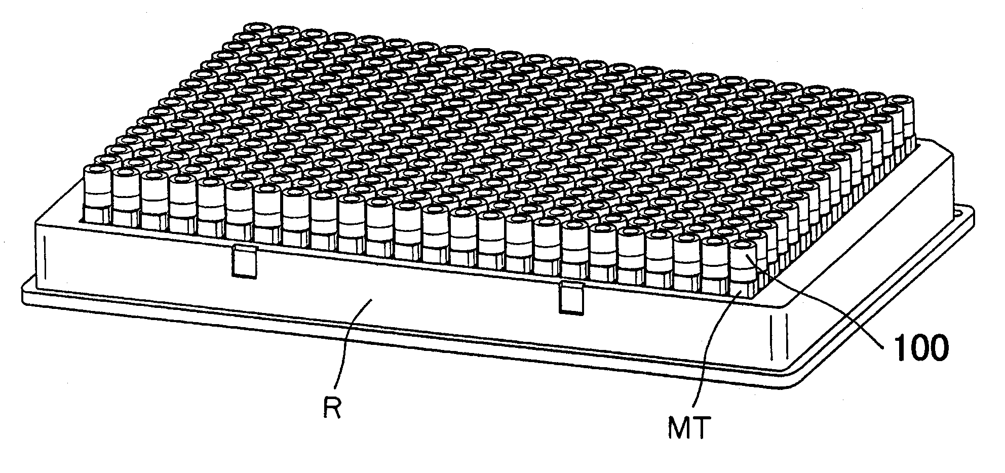
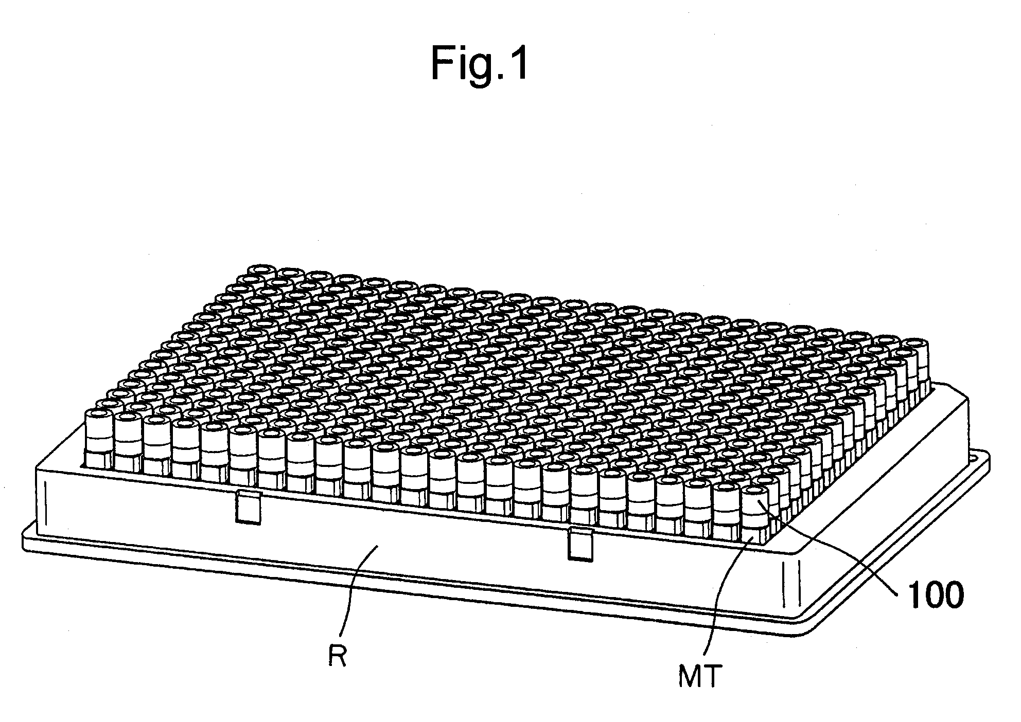
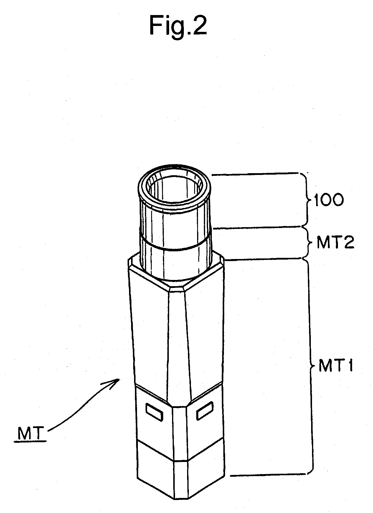
[0028]Caps for microtubes of the present invention are adapted to be presented in a correct orientation after the caps are aligned on an alignment plate by a cap alignment device having an alignment plate of the same pitch as a storage rack. The alignment plate is placed over the open-ended microtubes vertically accommodated storage rack, and the caps are simultaneously pushed out of the alignment plate toward the open ends of the microtubes to close the open ends. Each cap has a plug portion, which is inserted into the open end of the microtube and a grip portion having an outer circumferential diameter larger than an outer circumferential diameter of the plug portion, and protruding from the open end of the microtube. The entire length of the cap is longer than the pitch of the alignment plate and shorter than twice of the pitch. An upper edge of the grip portion of the cap has a collar with an outer circumferential diameter larger than the pitch of the alignment plate. The plug p...


PUM


Abstract

A cap for a microtube, which can be automatically aligned by an alignment plate for insertion in a correct orientation into the open end of the microtube held in a micro tube rack. The plate has partitions in a grid which produces a matrix of cells having a pitch defined by the spacing between the partitions. The cap 100 has an plug portion 120, which is adapted to be inserted into the open end of the microtube which is held in a rack having a matrix of wells congruent with the matrix of cells in the alignment plate. A grip portion 110 of the cap has an outer circumferential diameter larger than an outer circumferential diameter of the plug portion 120, so that when the cap is inserted in the microtube, the grip portion protrudes from the open end of the microtube. The entire length of the cap 100 is longer than the pitch of the alignment plate and shorter than twice the pitch. An upper edge of the grip portion 110 of the cap 100 has a collar 130 with an outer circumferential diameter larger than the pitch of the alignment plate. The plug portion 120 of the cap 100 has a taper 122 which is tapered toward a front end, and the center of gravity of the cap 100 is in the plug portion, so that the plug portion of the cap gravitates into one of the open cells of the alignment plate.

Description

FIELD OF INVENTION[0001]The present invention relates to a microtube for pharmaceutical development used for sealing samples in a field of researches of pharmaceutical development, and more specifically, it relates to a cap for a microtube having a shape suitable for aligning caps by an alignment plate having the same pitch as a storage rack for simultaneously capping and closing the open ends of a plurality of microtubes, accommodated in the wells of a microtube rack.BACKGROUND OF THE INVENTION[0002]In the field of research for pharmaceutical development, during tests, it is necessary to store a large number of samples at low temperature and to analyze them at high efficiency. Therefore, the storage and transportation of a storage rack has been carried out by sealing or encapsulating a sample-dissolved solution in a cylindrical- or a rectangular-tubular small vessel, called a microtube and depositing the microtubes into the storage rack partitioned into the total of 384 wells in a ...

Claims


Application Information

Patent Timeline
IPC IPC(8): B01L3/00
CPCB01L3/50825B01L3/50853B01L9/00B01L2300/0829B01L2300/041B01L2300/042B01L99/00
Inventor TSUTSUMI, KAZUHIRONISHII, HISAOUEYAMA, YUKIO
Owner TSUBAKIMOTO CHAIN CO
Why Eureka
Try Eureka