
Method and apparatus for jet-assisted drilling or cutting

Active Publication Date: 2009-09-10
UNIVERSITY OF MISSOURI
View PDF60 Cites 39 Cited by
  • Summary
  • Abstract
  • Description
  • Claims
  • Application Information

AI Technical Summary

Benefits of technology

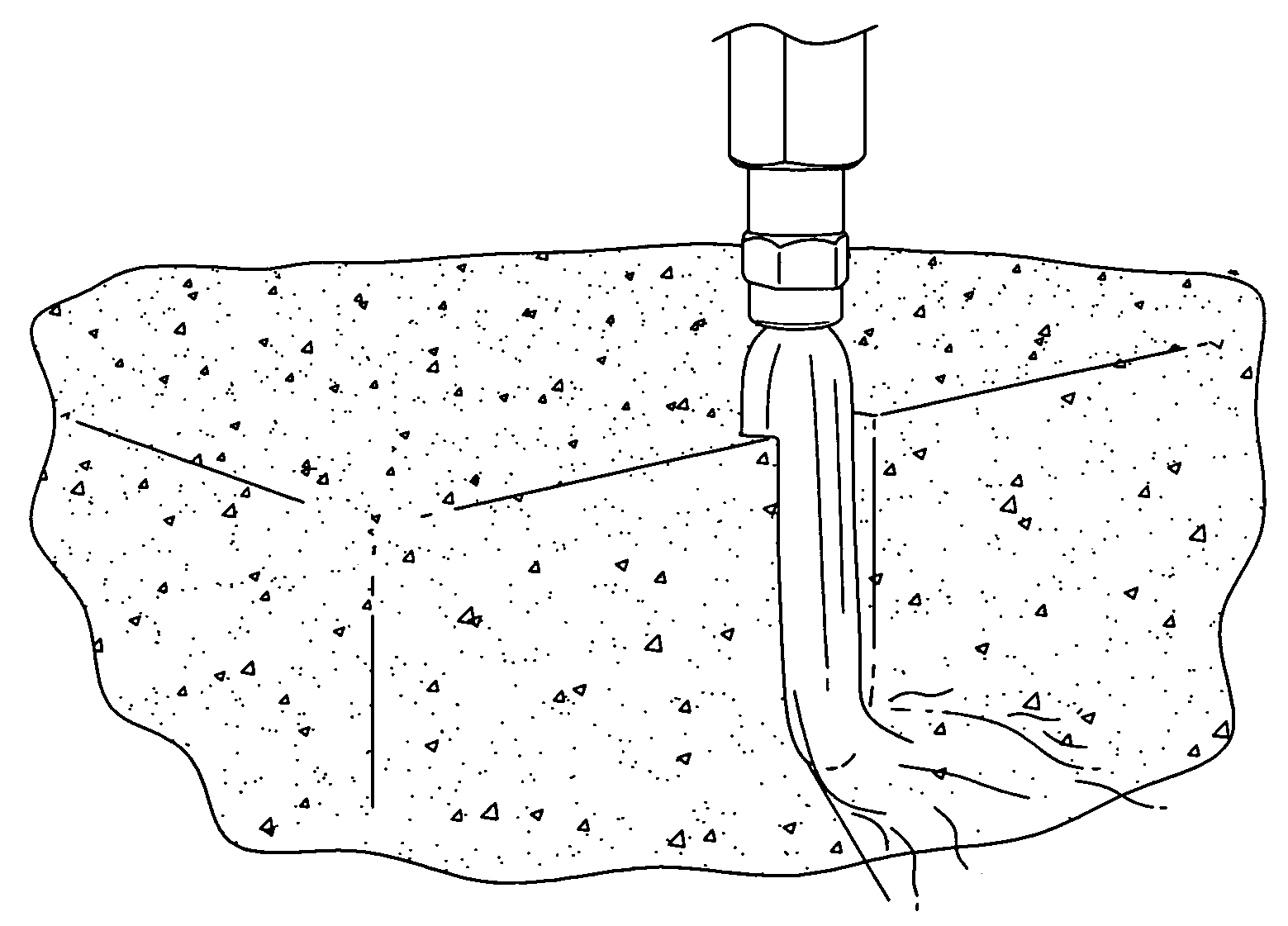
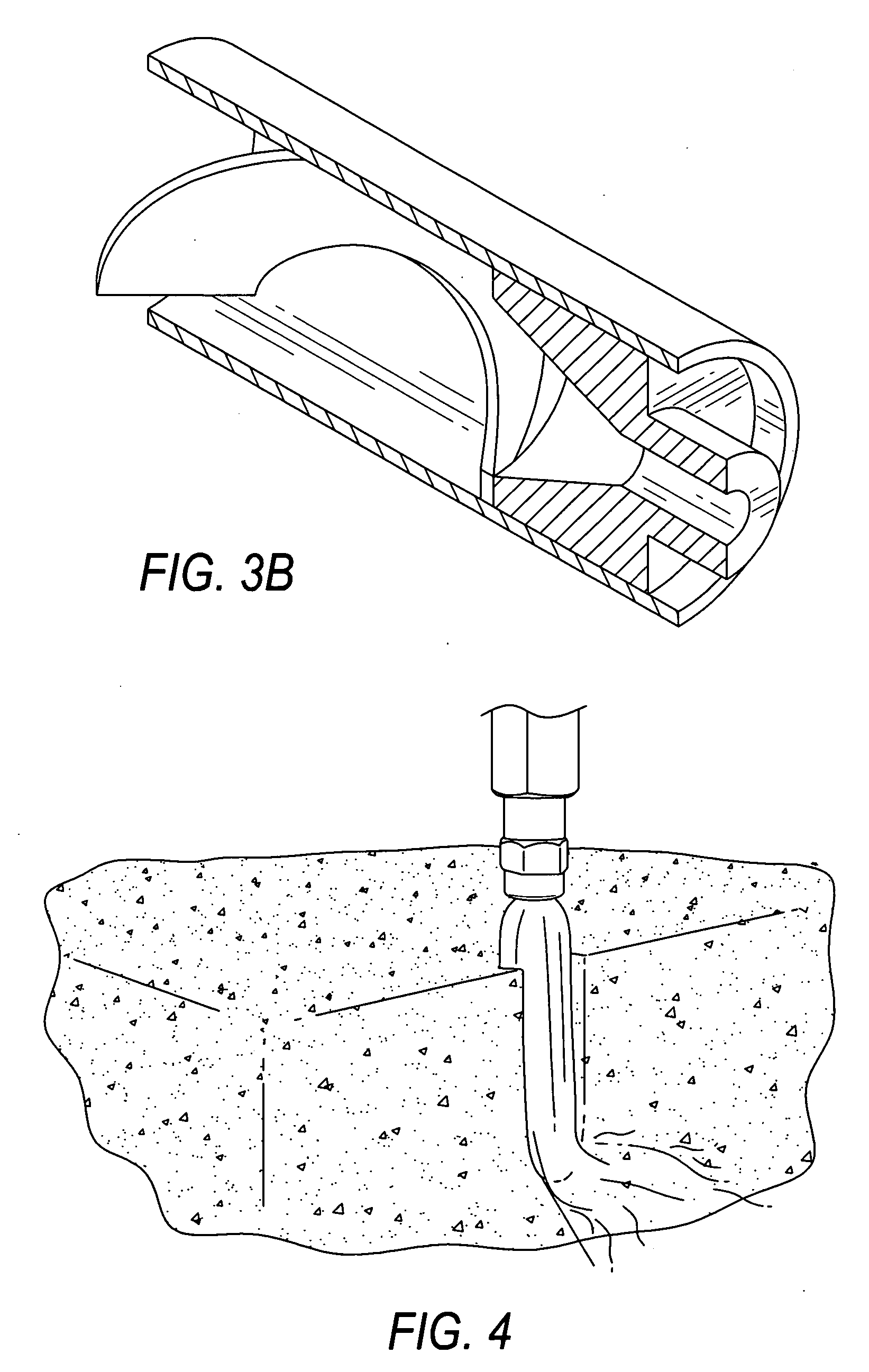
[0015]In one aspect of the invention, a novel jet-assisted drilling / cutting method utilizing a supercritical fluid / liquid carrying abrasive solids as a drilling or cutting fluid to increase efficiency and ease of removal of the drilling / cutting debris during a drilling or cutting operation is described. According to one embodiment of the invention, the inventive drilling or cutting method comprises 1) providing an abrasive-laden supercritical fluid / liquid under a pre-determined pressure, whereas said abrasive-laden supercritical fluid / liquid comprising a suspension of pre-selected abrasive solids in a supercritical fluid / liquid, 2) delivering said abrasive-laden supercritical fluid / liquid to an entrance point of a cutting nozzle capable of accelerating said abrasives, whereas existing from said cutting nozzle, said abrasive-laden supercritical fluid / liquid is discharged as an abrasive jet stream carried by gas, and 3) directing the abrasive jet stream at a target substance.
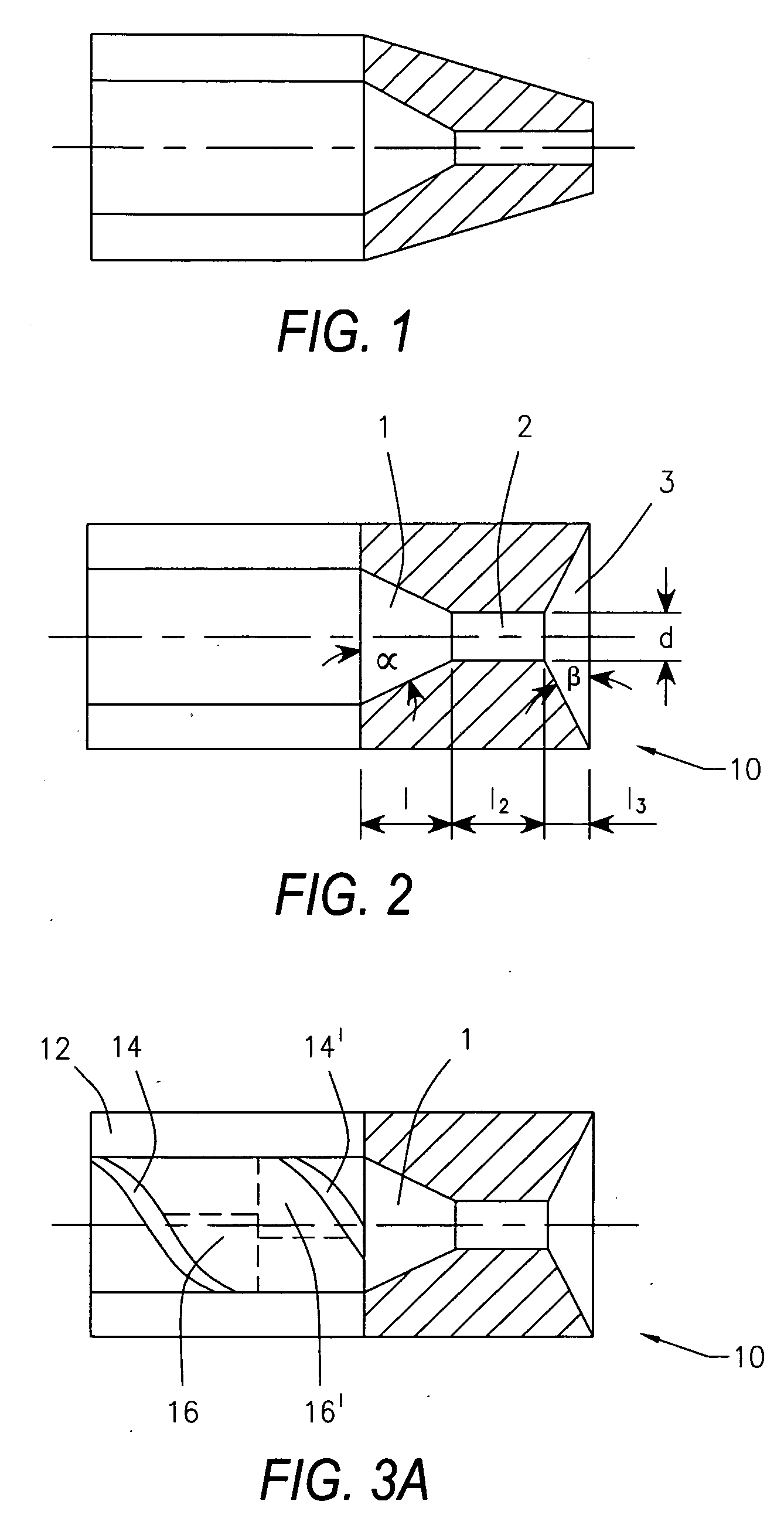
[0021]According to another embodiment of the invention, the inventive cutting nozzle may be incorporated into a nozzle assembly with a feeding section attached into or part of or preceding the inlet converging conic section of the cutting nozzle. The feeding section may further include a plurality (such as a pair, or multiplicity) of blades at a pre-arranged angle to tangentially induce a spinning vortex to the velocity of the abrasive-laden supercritical fluid / liquid before admitted into the cutting nozzle and to further widen the abrasive jet stream discharged from the cutting nozzle.
[0023]According to another embodiment of the invention, the nozzle discharge conditions, such as the discharge pressure and temperature, are carefully controlled. Minimizing restrictions to flow thereby lowers the discharge pressure; alternatively heating the nozzle and passing internal fluids may raise the exhaust temperature. Both control methods are to encourage instant gas or low-density supercritical-fluid formation in the nozzle or at discharge.

Problems solved by technology

While effective, the high-pressure fluid jet-assisted drilling technique still requires a means to transmit both force and high pressure fluid to the drilling bit, and thereby makes the supporting drill rod stiffer and more difficult to turn.
Energy transfer from the water to the particles is, however, inefficient, so that the particles gain only a fraction of the velocity that the liquid jet would have without them.
The requirement of a very high water pressure to cut some rock targets is problematic, especially when the drill is attached to the end of a coiled-tube system, since the thin wall of such a pipe can only safely carry a certain pressure and still perform its function.
If this is done, and water injected through it, then the swirling action of the water jet stream can induce cavitation in the central section of the resulting water jet stream, with the collapse of the cavitation cloud enhancing cutting performance, but still at a relatively slow penetration rate.
The latter systems do not have sufficient power, as normally applied, to be able to cut into rock and similar target material.
Concurrently, in developing a design for a light, portable and simple drill, the need for a rotation system to ensure that abrasive jets fully sweeps the area ahead of the nozzle and drill assembly to remove any impeding rock, adds considerable complexity, cost and weight to the unit.
By increasing the down-hole pressure around the drilling bit, however, a higher driving pressure is required to effectively cut into the rock target, that may well be in the range from 50 to 200 MPa and this exceeds the pressure capability of most coiled tubing.
In passing through this barrier the performance of the jet is degraded, and a poor cutting ability in penetrating the target rock results.
The solids are neither hard nor dense resulting in inefficient cutting.

Method used


Image

  • Method and apparatus for jet-assisted drilling or cutting
  • Method and apparatus for jet-assisted drilling or cutting
  • Method and apparatus for jet-assisted drilling or cutting

Examples


Embodiment Construction

[0031]The embodiments discussed herein are merely illustrative of specific maimers in which to make and use the invention and are not to be interpreted as limiting the scope of the instant invention.

[0032]While the invention has been described with a certain degree of particularity, it is to be noted that many modifications may be made in the details of the invention's constriction and the arrangement of its components without departing from the spirit and scope of this disclosure. It is understood that the invention is not limited to the embodiments set forth herein for purposes of exemplification.

[0033]Unless otherwise defined, all technical and scientific terms used herein have the same meaning as commonly understood by one of ordinary skill in the art to which this invention belongs. All publications, patent applications, patents, and other references mentioned herein are incorporated by reference in their entirety.

[0034]The present invention employs supercritical fluids / liquids...


PUM

PropertyMeasurementUnit
Densityaaaaaaaaaa
Abrasiveaaaaaaaaaa

Abstract

An abrasive cutting or drilling system, apparatus and method, which includes an upstream supercritical fluid and / or liquid carrier fluid, abrasive particles, a nozzle and a gaseous or low-density supercritical fluid exhaust abrasive stream. The nozzle includes a throat section and, optionally, a converging inlet section, a divergent discharge section, and a feed section.

Description

CROSS-REFERENCE TO RELATED APPLICATIONS[0001]This application claims priority to U.S. Provisional Application No. 61 / 068,935, filed Mar. 10, 2008, which is herein incorporated by reference.GRANT STATEMENT[0002]The invention was made in part from government support under Grant No. DE-FC26-04NT15476 from the Department of Energy. The U.S. Government has certain rights in the invention.BACKGROUND OF THE INVENTION[0003]1. Field of the Invention[0004]The present invention relates to a method and apparatus for cutting into and drilling through materials in general. More specifically, the present invention relates to a method and apparatus for cutting into and drilling through materials using the liquid, gaseous and / or supercritical phase of a fluid along with certain solid abrasive materials.[0005]2. Prior Art[0006]Jet assisted drilling for drilling horizontal holes, primarily for oil and gas wells, has been attempted since at least the 1960s, but required high-pressure to increase penetr...

Claims


Application Information

Patent Timeline
IPC IPC(8): B24C1/00B24C3/00
CPCE21B7/18B24C11/005
Inventor SUMMERS, DAVID ARCHIBOLDWOELK, KLAUS HUBERTOGLESBY, KENNETH DOYLEGALECKI, GRZEGORZ
Owner UNIVERSITY OF MISSOURI
Learn More