Netting framework of a fiber-made racket

a fiber-made racket and netting technology, applied in the field of netting framework of fiber-made rackets, can solve the problems of slow weaving with the threads, inconvenience, etc., and achieve the effects of reducing contact area, facilitating thread passing, and increasing speed

Inactive Publication Date: 2009-09-10
CHANG CHEN CHUNG
View PDF9 Cites 6 Cited by
  • Summary
  • Abstract
  • Description
  • Claims
  • Application Information

AI Technical Summary

Benefits of technology

[0006]In this invention, the netting structure of a racket made of a fibrous material is provided, comprising a racket frame and a supporting part. The racket frame is integrally formed with upper and lower racket frames that are made of the fibrous material, and internal and external penetration netting areas are integrally formed around between the upper and lower racket frames. Several supporting parts are provided in the netting area, a couple of parts that are adjacent to each other are lengthways stationary in the netting area of racket, and thus the threads of the racket pass through the couple of supporting parts and cross vertically and horizontally in the racket frame to form a hit area. With the netting areas of racket frame and the supporting parts between the areas, it is easy to pass the threads at a higher speed. The net threads pass through the supporting part to reduce the area of contact with the racket frame and thus relatively increase the flexibility of hit area of the racket when hitting a ball.

Problems solved by technology

However, the conventional racket netting is achieved necessarily through the quite minute drill holes 2, so it is quite inconvenient and slow to weave with the threads.

Method used


Image

  • Netting framework of a fiber-made racket
  • Netting framework of a fiber-made racket
  • Netting framework of a fiber-made racket

Examples


second embodiment

[0023]With reference to FIG. 6 as a sectional view illustrating the supporting part integrated into the racket frame in this invention, the structure and function is approximately the same as that in the preferred embodiment of this invention, and what is different is in that the supporting part 20 is a cylindrical rod made of the metallic material, of which a middle annular portion that shrinks is formed with an arc-shaped shift limit concave 24. The supporting parts 20 are stationary separately at concave portions 25 and 26 that are formed at two adequate intervals around the upper and lower ends of the upper and lower racket frames 11 and 12. The concave portions 25 and 26 may be dots or rings. In the embodiment, the concave portions 25 and 26 are rings so that the supporting parts 20 may be placed in a formed model, and then the protruding portions 231 may be used as a basic level to fix the upper racket frame 11 with the lower racket frame 12 and enhance the intensity of format...

third embodiment

[0024]With reference to FIG. 7 as a view illustrating the appearance of partial structure where the supporting part is integrated into the racket frame in this invention, the structure and function is approximately the same as that in the preferred embodiment of this invention, and what is different is in that the supporting part 20 is a cylindrical rod made of a composite material, around which a damper sheath 40 made of a rubber wraps. A lengthwise cut groove 41 is formed axially at a side of the damper sheath 40 and gradually shrinks towards the radial center of annular damper sheath 40 to form an arc-shaped shift limit groove 42 so that the net thread 30 may get into the shift limit groove 42 to be fixed, and thus the damper sheath 40 is tightened to enhance the intensity of support to the hit area 31.

fourth embodiment

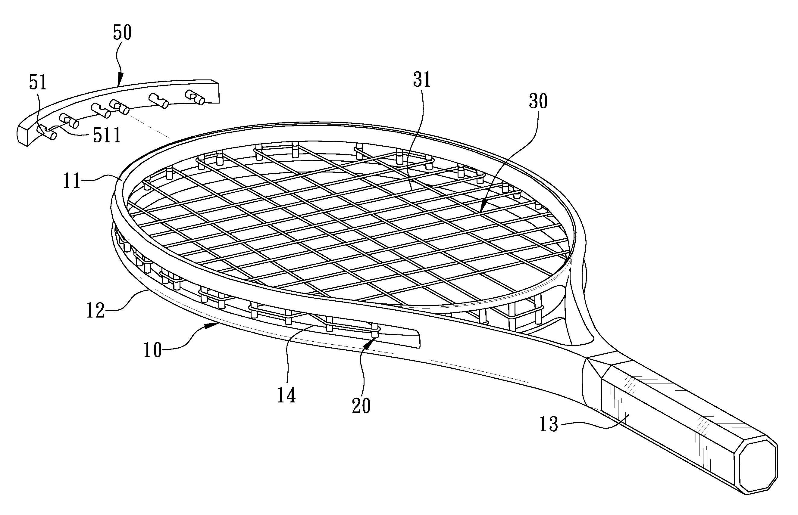
[0025]With reference to FIG. 8 illustrating this invention, the structure and function is approximately the same as that in the preferred embodiment of this invention, and what is different is in that an all-in-one ornament strip 50 made of plastics are formed at a top side of the grasp portion 13 opposite to the netting area 14 of the racket frame 10. Several clamping strips 51 are provided at a side of the supporting parts 20 corresponding to the ornament strip 40. The clamping strips 51 are cylindrical sleeve, and a notch 511 is formed corresponding to each of the sides of supporting parts 20 for the clamping strips 51 to wedge the supporting parts 20. The other side of the ornament strip 40 is exposed to an outside of the netting area 14, where an advertisement typeface character or pattern blueprint may be printed.

[0026]Here, the features and attainable expected effects of this invention are described again below:[0027]1. The racket frame and supporting parts according to this ...


PUM


Abstract

The netting structure of a fiber-made racket comprises a racket frame and several supporting parts. The racket frame is formed with upper and lower racket frames made of the fibrous material, and internal and external penetration netting areas are formed around between the upper and lower racket frames. Several supporting parts are provided in the netting area, a couple of parts adjacent to each other are lengthways stationary in the netting area of racket, and the threads of the racket pass through the couple of supporting parts and cross vertically and horizontally in the racket frame to form a hit area. Thanks to the interval of distance of thread passing between the netting area and the supporting parts, it is easy and fast to pass the threads, reducing the area of net threads contacting with the racket frames to increase the flexibility of hit area at the time of hitting.

Description

BACKGROUND OF THE INVENTION[0001]1. Field of the Invention[0002]This invention relates to the framework of a racket and particularly to the netting framework of a fiber-made racket.[0003]2. Description of Related Art[0004]With reference to FIG. 1 illustrating the appearance of a conventional racket made of a fibrous material, a racket frame 1 that is made of a fibrous material is placed in a predetermined molding tool, and the molding tool is heated in a manner of air blowing to form the frame by heat curing; after it is formed, highly concentrated piercing drill holes 2 are formed around the racket frame 1, through which net threads correspondingly pass in order, and the threads cross vertically and horizontally inside the racket frame 1 to form a hit area 4 for achievement of the netting. However, the conventional racket netting is achieved necessarily through the quite minute drill holes 2, so it is quite inconvenient and slow to weave with the threads. After the racket frame is...

Claims


Application Information

Patent Timeline
Patent Type & Authority Applications(United States)
IPC IPC(8): A63B51/00
CPCA63B49/002A63B49/007A63B49/02A63B2209/023A63B49/14A63B51/00A63B59/0092A63B49/10A63B49/022A63B49/025A63B49/028A63B60/54
Inventor CHANG, CHEN-CHUNG
Owner CHANG CHEN CHUNG
Why Eureka
Try Eureka