
Device And Method For Filling A Container With A Gas Under Pressure

Active Publication Date: 2009-09-17
LAIR LIQUIDE SA POUR LETUDE & LEXPLOITATION DES PROCEDES GEORGES CLAUDE
View PDF10 Cites 57 Cited by
  • Summary
  • Abstract
  • Description
  • Claims
  • Application Information

AI Technical Summary

Benefits of technology

[0008]The present invention provides a device for filling a container with a gas under pressure, comprising at least one source of gas pressurized to a first pressure, called high pressure, a transfer circuit capable of selectively connecting the source or sources of pressurized gas to the tank to be filled, the transfer circuit comprising control members for controlling the flow of the gas from the source or sources to the tank, the transfer circuit further including at least one cooling exchanger, for cooling the pressurized gas. More specifically, the present invention provides a device for filling a container with a gas under pressure, especially hydrogen in a tank of a vehicle, comprising at least one source of gas pressurized to a first pressure, called high pressure, a transfer circuit capable of selectively connecting the source or sources of pressurized gas to the tank to be filled, the transfer circuit comprising control members for controlling the flow of the gas from the s

Problems solved by technology

The filling must be carefully controlled since rapid pressurization of the gas causes heating, which may become incompatible with the constituent material of the tank (for example temperatures above 85° C.).
However, this solution has the drawback of lengthening the time to fill the tank.
However, this solution requires substantial and costly infrastructures, in particular in terms of electrical energy.
However, in certain situations, precooling the pressurized gas is difficult to control at low cost.
Moreover, the known heat exchange means are relatively bulky.

Method used


Image

  • Device And Method For Filling A Container With A Gas Under Pressure
  • Device And Method For Filling A Container With A Gas Under Pressure
  • Device And Method For Filling A Container With A Gas Under Pressure

Examples


Embodiment Construction

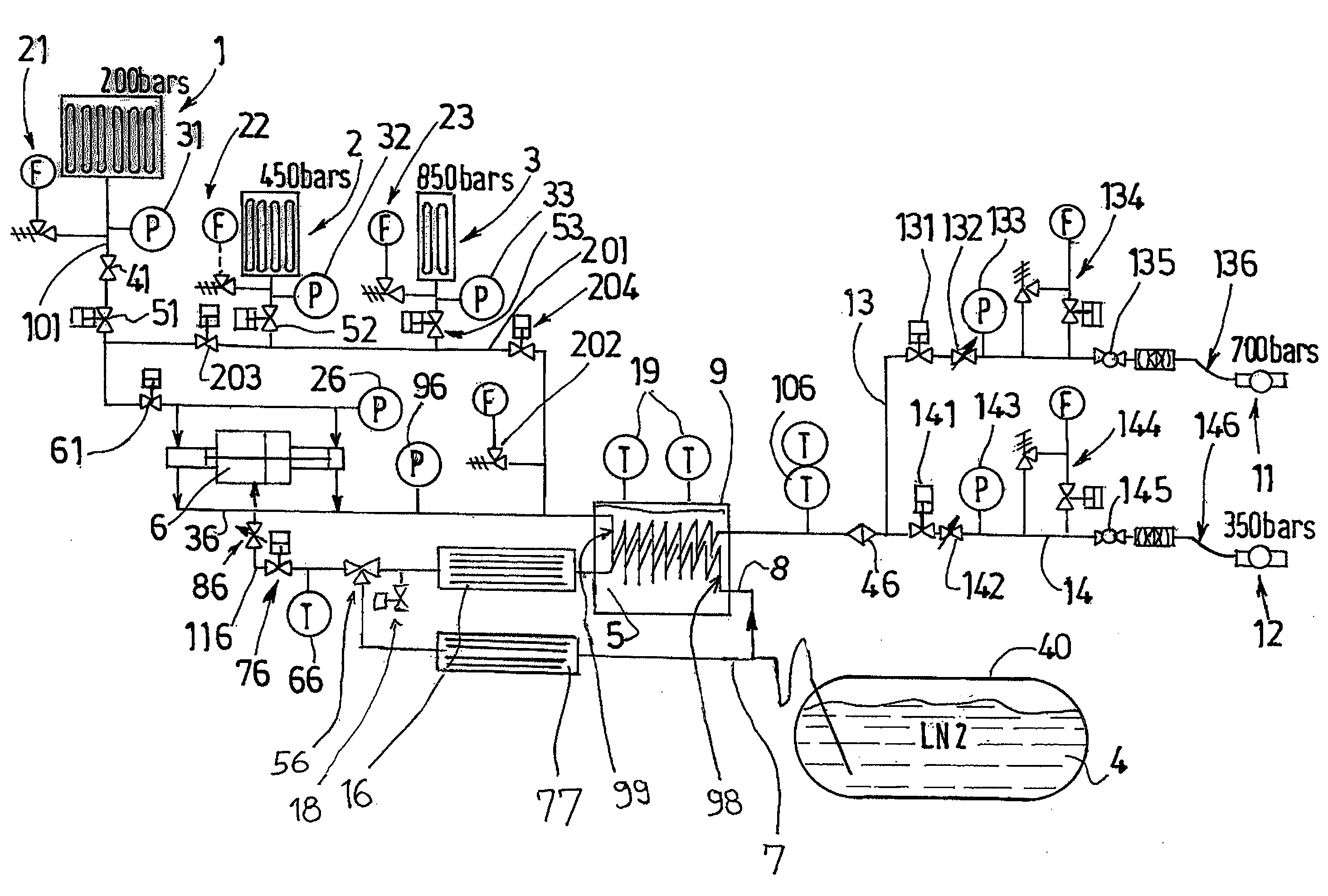
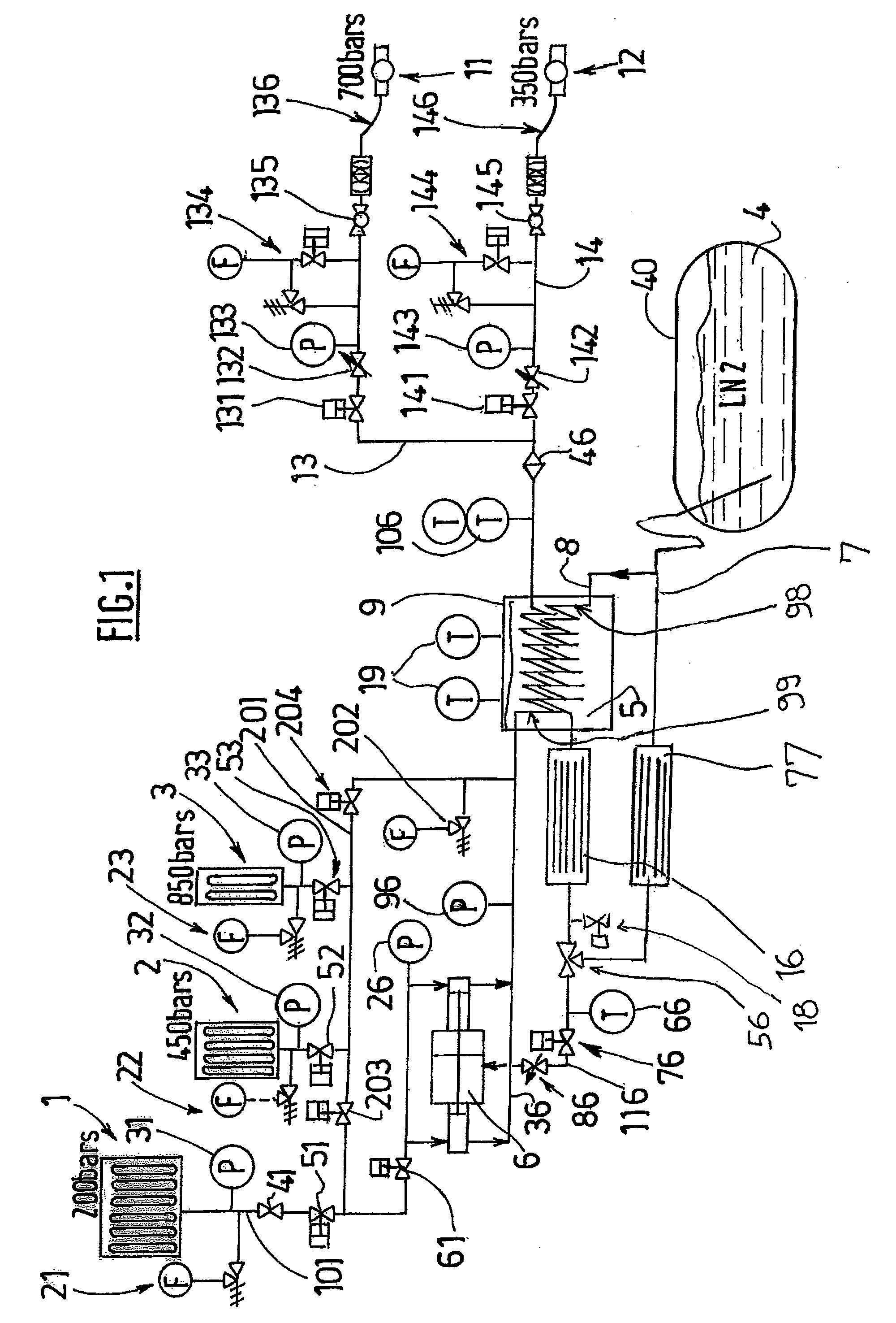
[0013]The device according to the present invention, which is consistent with the definition given in the above preamble, is essentially one in which the cooling exchanger comprises a hot flow circuit for the pressurized gas to be cooled, a cold flow circuit for a cold cooling fluid, and a refrigeration hold-over medium, the refrigeration hold-over medium being in direct heat exchange, on the one hand, with the cold fluid of the cold circuit and, on the other hand, with the pressurized gas to be cooled of the hot circuit, in order to selectively carry out indirect heat exchange between the pressurized gas and the cold fluid via the refrigeration hold-over medium, and in which the refrigeration hold-over medium forms and fills a gap between the cold fluid of the cold circuit and the pressurized gas of the hot circuit, the gap having a thickness of greater than 5 mm.

[0014]The invention therefore serves especially to guarantee very good temperature stability of the pressurized gas at t...


PUM

PropertyMeasurementUnit
Temperatureaaaaaaaaaa
Lengthaaaaaaaaaa
Lengthaaaaaaaaaa

Abstract

Device for filling a container with a gas under pressure, especially hydrogen in a tank of a vehicle, comprising at least one source (1, 2, 3, 6) of gas pressurized to a first pressure, called high pressure, a transfer circuit (201, 36, 13, 14, 136, 146) capable of selectively connecting the source or sources (1, 2, 3, 6) of pressurized gas to the tank to be filled, the transfer circuit comprising control members (204, 132, 142) for controlling the flow of the gas from the source or sources (1, 2, 3, 6) to the tank, the transfer circuit further including at least one cooling exchanger (9), for cooling the pressurized gas, wherein the cooling exchanger (9) comprises a hot flow circuit (99) for the pressurized gas to be cooled, a cold flow circuit (98) for a cold cooling fluid, and a refrigeration hold-over medium (5), the refrigeration hold-over medium (5) being in direct heat exchange, on the one hand, with the cold fluid of the cold circuit (98) and, on the other hand, with the pressurized gas to be cooled of the hot circuit (99), in order to selectively carry out indirect heat exchange between the pressurized gas and the cold fluid (4) via the refrigeration hold-over medium (5), and wherein the refrigeration hold-over medium (5) forms and fills a gap (1) between the cold fluid of the cold circuit (98) and the pressurized gas of the hot circuit (99), the gap (1) having a thickness of greater than 5 mm and preferably between 20 and 50 mm.

Description

[0001]This application claims priority to French Patent Application FR 0851560 filed Mar. 11, 2008, incorporated herein in its entirety.FIELD OF INVENTION[0002]The present invention relates to a device and a method for filling a container with a gas under pressure. The invention relates in particular to the filling of vehicle tanks with gaseous hydrogen.BACKGROUND OF THE INVENTION[0003]The storage of gaseous hydrogen at high pressures is particularly important for its use in automobiles. In addition, in this application in particular, the relative rapidness with which a tank is filled is an important factor. Specifically, the operation of filling hydrogen tanks on board vehicles having a fuel cell or an internal combustion engine operating on hydrogen must be able to be carried out in at most a few minutes. The filling must be carefully controlled since rapid pressurization of the gas causes heating, which may become incompatible with the constituent material of the tank (for exampl...

Claims


Application Information

Patent Timeline
IPC IPC(8): F17C5/06B67D5/04B67D7/04
CPCF17C5/06Y02E60/321F17C13/025F17C13/026F17C2221/012F17C2223/0123F17C2223/036F17C2225/0123F17C2225/036F17C2227/0164F17C2227/0341F17C2227/0388F17C2227/043F17C2250/03F17C2250/043F17C2250/0439F17C2250/0631F17C2260/023F17C2270/0139F17C2270/0171F17C2270/0178F17C7/00Y02E60/32F17C5/007
Inventor ALLIDIERES, LAURENTCHARBONNEAU, THOMASSEQUEIRA, SEBASTIANVINARD, THOMAS
Owner LAIR LIQUIDE SA POUR LETUDE & LEXPLOITATION DES PROCEDES GEORGES CLAUDE
Features
  • Generate Ideas
  • Intellectual Property
  • Life Sciences
  • Materials
  • Tech Scout
  • Unparalleled Data Quality
  • Higher Quality Content
  • 60% Fewer Hallucinations
Learn More