
Concrete funnel and placement system

a funnel and concrete technology, applied in the direction of chutes, liquid transfer devices, liquid handling, etc., can solve the problems of inconvenient use, large difficulty in pouring concrete, and ordinary concrete chutes are often inconvenient and difficult to use, so as to accurately control the flow of concrete

Active Publication Date: 2009-09-17
ROYCE INNOVATIONS
View PDF31 Cites 15 Cited by
  • Summary
  • Abstract
  • Description
  • Claims
  • Application Information

AI Technical Summary

Benefits of technology

[0018]The size or the shape of the aperture of the funnel element may be selectively adjustable to accurately control the flow of concrete. Further, the funnel element can have at least one handle. The concrete funnel and placement system could include a remote operating mechanism allowing an operator to rotate or adjust the funnel-type apparatus from a cab of a mixer truck or other location. Also, the funnel-type apparatus may be constructed of a light-weight, non-reactive polymer, plastic or metal.

Problems solved by technology

These ordinary concrete chutes are often inconvenient and difficult to use, especially if the concrete is intended for deposit in a narrow or irregularly-shaped form or in a form where the dimensions are exceptionally small.
While these forms are very useful, they are difficult to make.
The tight space confines in these and other closely confined areas lead to great difficulties while pouring concrete.

Method used


Image

  • Concrete funnel and placement system
  • Concrete funnel and placement system
  • Concrete funnel and placement system

Examples


Embodiment Construction

[0040]The devices and methods discussed herein are merely illustrative of specific manners in which to make and use this invention and are not to be interpreted as limiting in scope.

[0041]While the devices and methods have been described with a certain degree of particularity, it is to be noted that many modifications may be made in the details of the construction and the arrangement of the devices and components without departing from the spirit and scope of this disclosure. It is understood that the devices and methods are not limited to the embodiments set forth herein for purposes of exemplification.

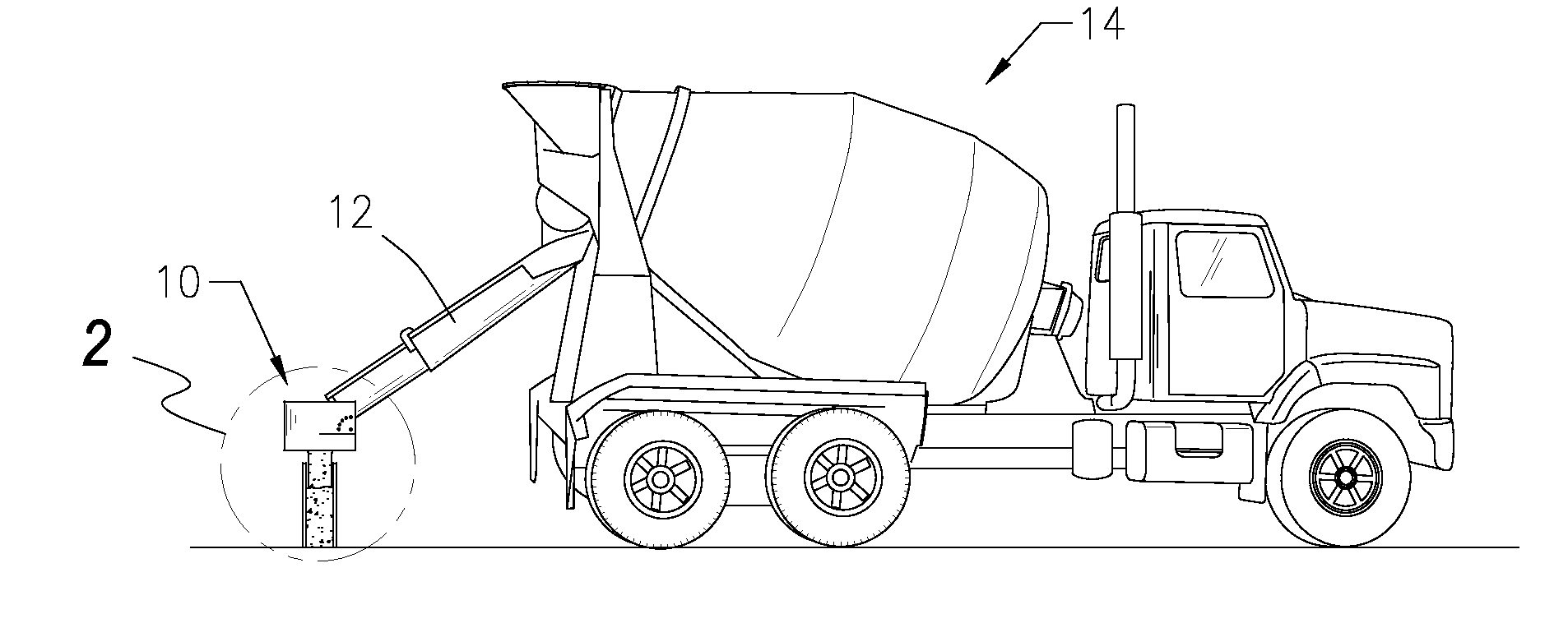
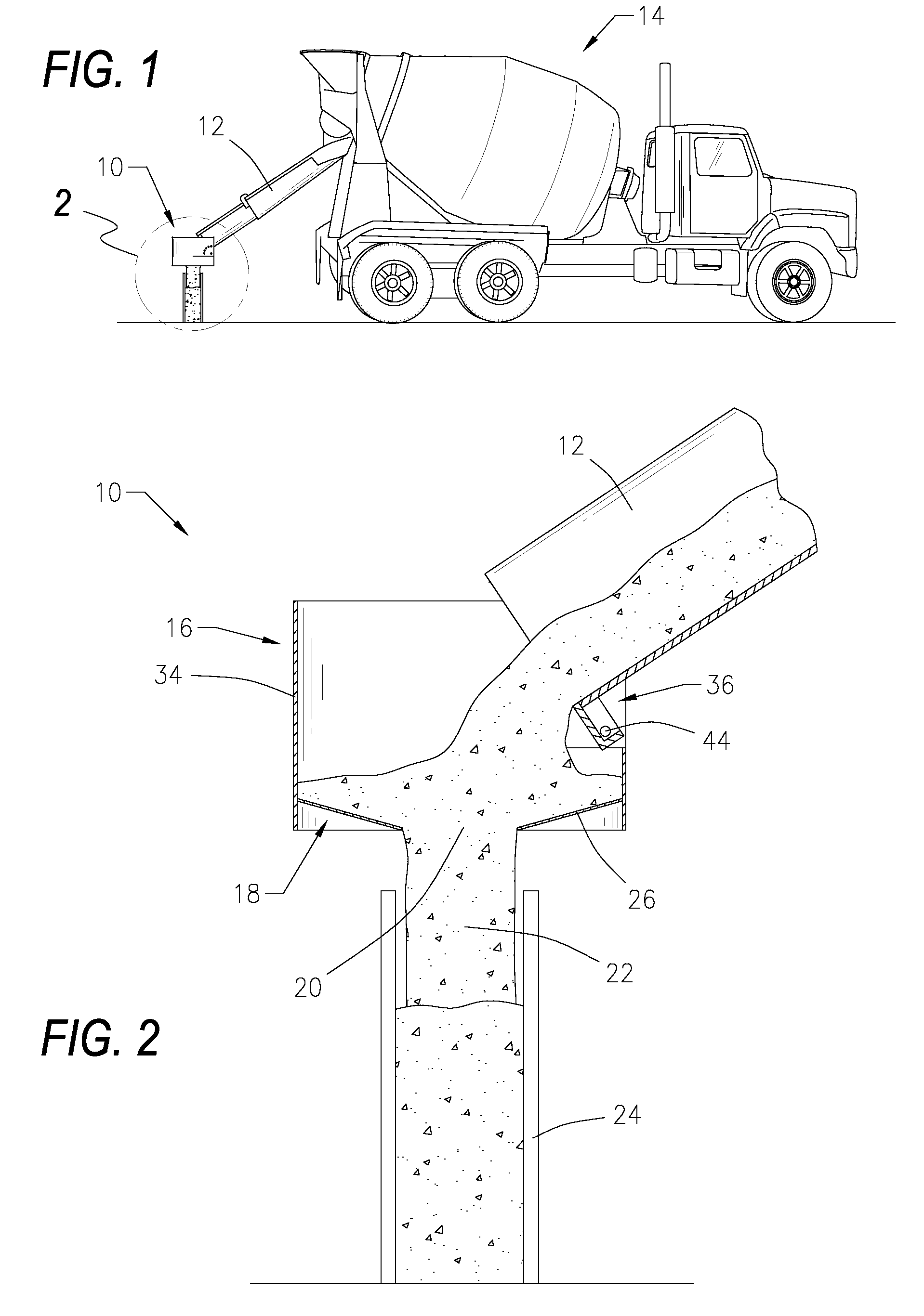
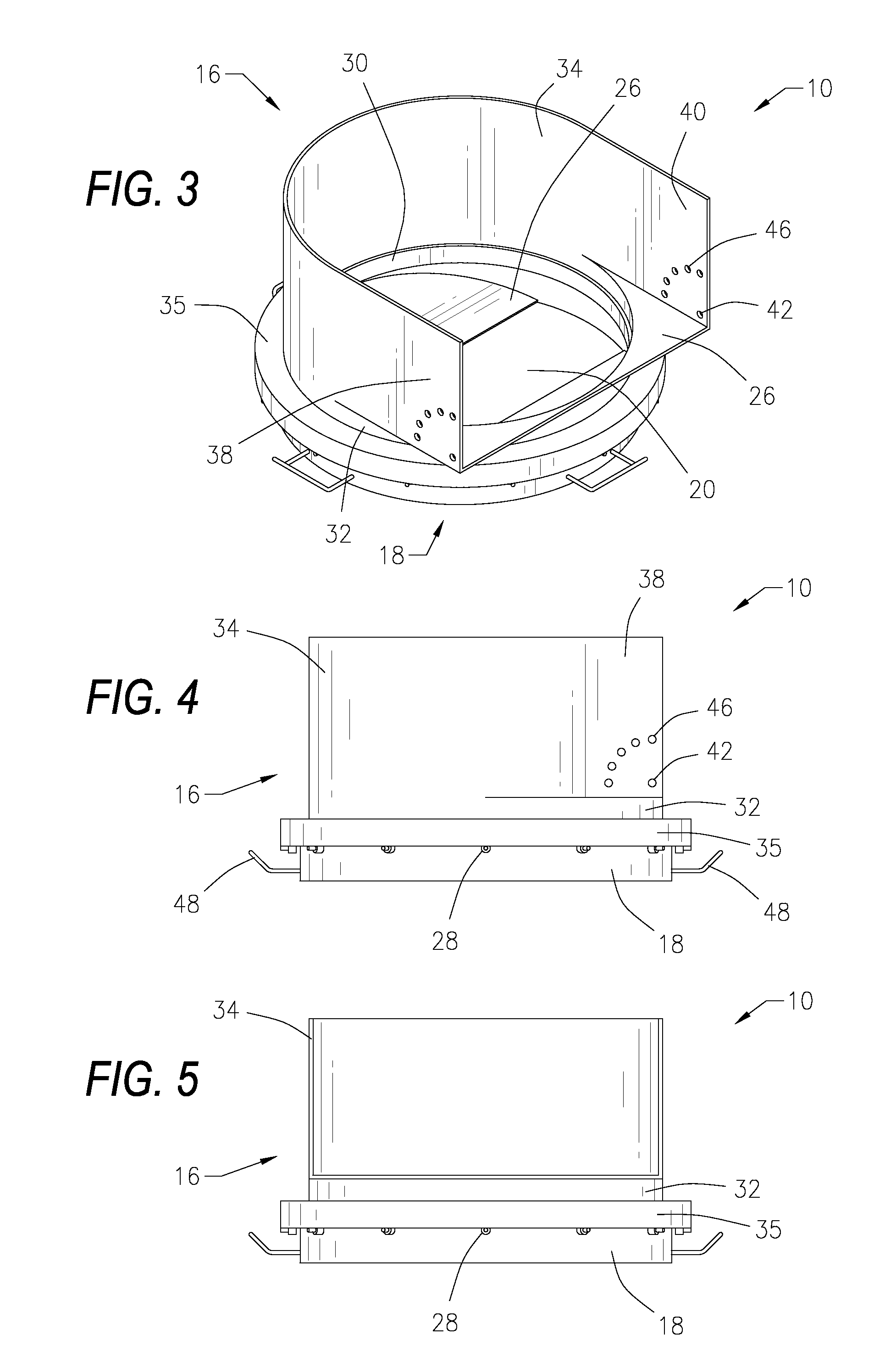
[0042]Referring to the figures of the drawings, wherein like numerals of reference designate like elements throughout the several views, and initially to FIG. 1, a concrete placement and funnel system comprising a funnel-type apparatus 10 removably secured to a concrete chute 12 on the rear end of a mixer truck 16. Existing concrete chutes 12 may be retrofitted or utilized with the f...


PUM

PropertyMeasurementUnit
Angleaaaaaaaaaa
Weightaaaaaaaaaa
Angleaaaaaaaaaa

Abstract

A concrete funnel and placement system comprising a funnel-type apparatus removably securable to a concrete chute having a retainer element coupled to a funnel element. The funnel element includes a downwardly sloping base forming an aperture for concrete to flow through. The aperture may be any shape or size, and one or more interchangeable discharge plates may be included in order to selectively change the shape and / or size of the aperture. Further, the aperture of the funnel element may be selectively opened or closed. Bearings, sprockets, rollers or other rotatable mechanisms may be included to allow the funnel element to rotate 360° with respect to the retainer element. The retainer element may include a gasket forming a seal with the funnel element to prevent concrete from impeding rotation. The retainer element may be hingedly secured to the concrete chute allowing the retainer element to be adjusted such that it is substantially horizontal while pouring concrete, independent of the angle of the concrete chute. The funnel-type apparatus may be in communication with the concrete truck, thus allowing the rotation and adjustment of the funnel-type apparatus to be controlled by electronics, such that the operator may be located in the cab of the truck or other location.

Description

CROSS-REFERENCE TO RELATED APPLICATIONS[0001]This application claims priority to and is a continuation-in-part of U.S. application Ser. No. 12 / 047,898, filed Mar. 13, 2008, which is incorporated herein by reference.BACKGROUND OF THE INVENTION[0002]1. Field of the Invention[0003]This invention relates generally to a concrete funnel and placement system, and more particularly to a funnel-type apparatus removably securable to a concrete chute comprising a retainer element coupled to a funnel element having an aperture for directing the flow of concrete to a desired location.[0004]2. Description of the Related Art[0005]It is common practice to make concrete in a transit-mixer truck during transit from a supply station to a worksite and to dispense the mixed slurry of concrete by means of an elongate, rigid, upwardly opening U-shaped metal concrete chute having a receiver end related to the discharge end of a mixing drum rotatably mounted relative to the transit-mixture truck and a disch...

Claims


Application Information

Patent Timeline
IPC IPC(8): B67C11/00B28C7/00
CPCB28C5/4244E04G21/025B28C7/168
Inventor ROYCE, TREVOR
Owner ROYCE INNOVATIONS
Learn More