
Model based wind turbine drive train vibration damper

a technology of vibration damper and wind turbine, which is applied in the direction of rotors, electric generator control, vessel construction, etc., can solve the problems of not providing the reliability necessary, heavy mechanical wear, and considerably higher production costs, and achieve the effect of reducing mechanical oscillation

Active Publication Date: 2009-09-17
GENERAL ELECTRIC CO
View PDF7 Cites 31 Cited by
  • Summary
  • Abstract
  • Description
  • Claims
  • Application Information

AI Technical Summary

Benefits of technology

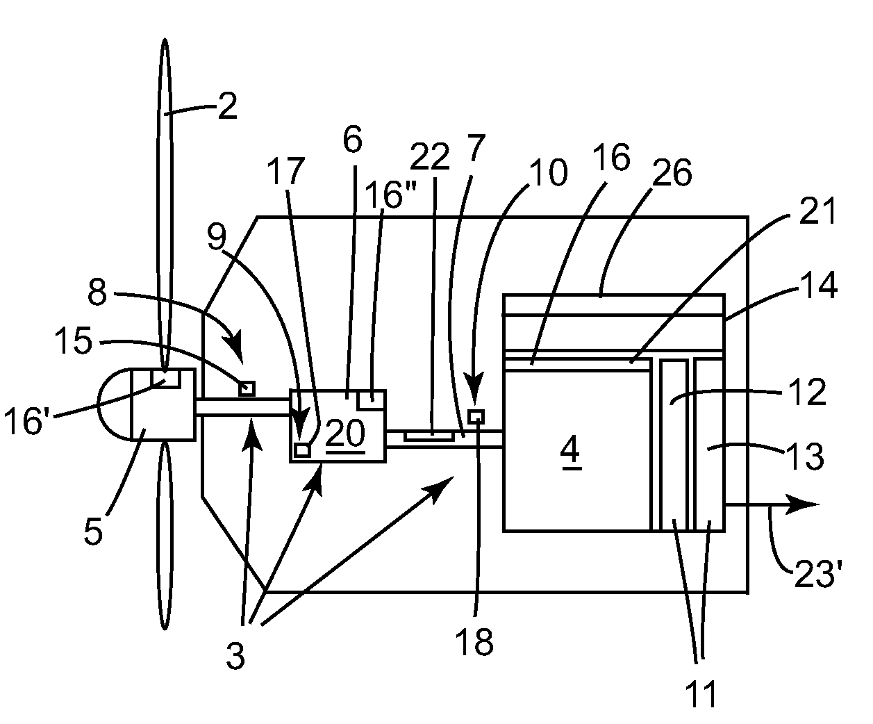
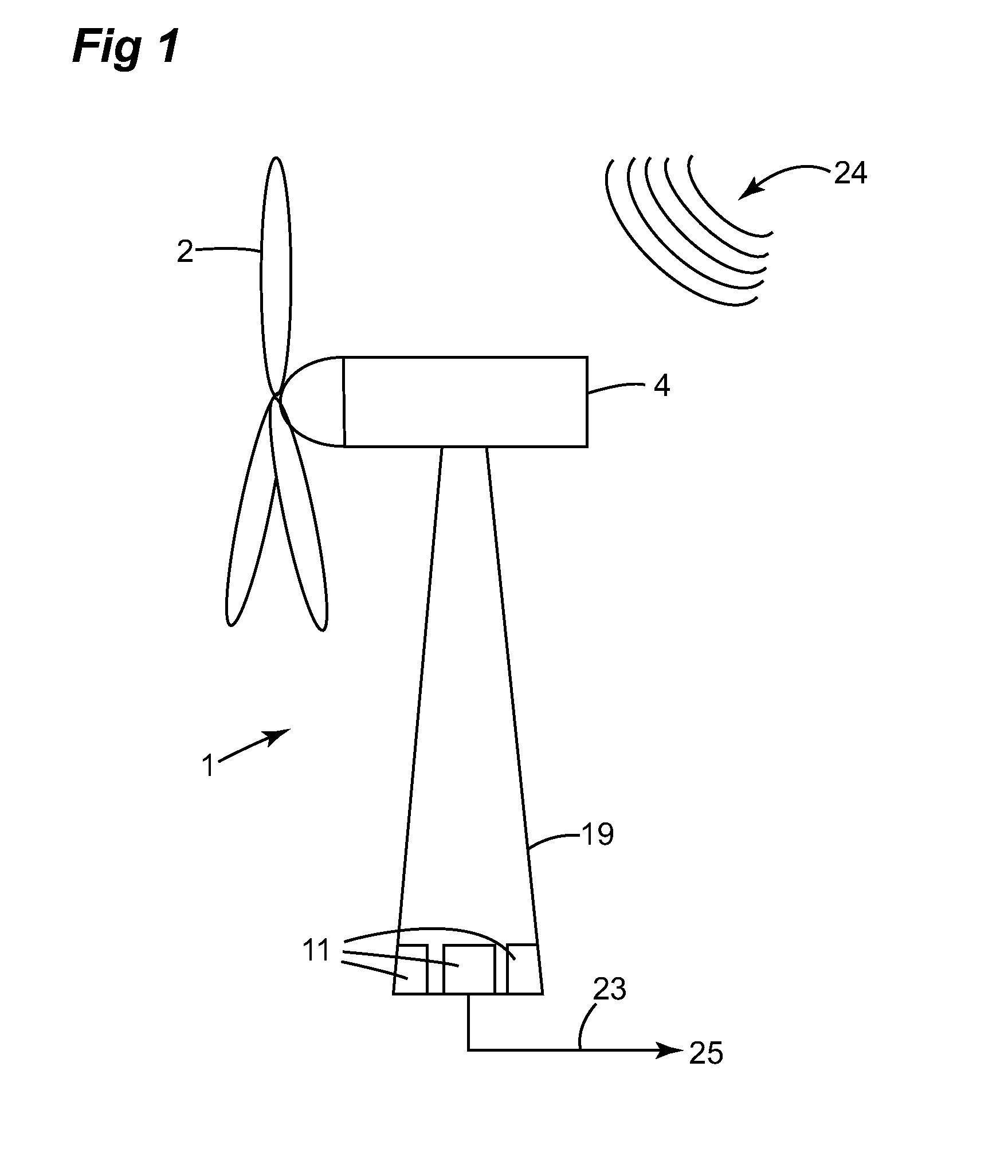
[0009]According to embodiments described herein, the mechanical stress, which is understood to be forces or torques caused by wind acting onto the fixed, moveable or rotatable parts of the wind power plant, is reduced. Accordingly mechanical wear of these parts of the wind power plant can be substantially reduced.
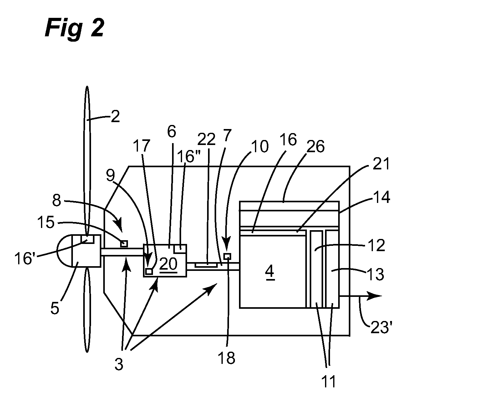
[0038]With help of the electronic torque control, the electric generator of the wind power plant can be used for actively providing torques and / or forces to the wind turbine drive train and in this way for damping or canceling vibrations or oscillations at mechanically sensitive areas.

Problems solved by technology

In particular, highly turbulent or unsteady wind conditions may introduce vibrations and oscillations into the wind power plant and thus may lead to heavy mechanical wear thereof.
This however leads to considerably higher production costs and may still not provide for the necessary reliability as expected from these systems.
Thus, larger dimensioning of the parts and increasing the material strength may reduce the competitiveness of wind power plants in comparison to other ways of generating energy and thus may not provide for a satisfying solution.

Method used


Image

  • Model based wind turbine drive train vibration damper
  • Model based wind turbine drive train vibration damper
  • Model based wind turbine drive train vibration damper

Examples


Embodiment Construction

[0007]A full and enabling disclosure of the present invention including the best mode thereof, to one of ordinary skill in the art is set forth more particularly in the remainder of the specification, including reference to the accompanying figures. Reference will now be made in detail to the various embodiments of the invention, one or more examples of which are illustrated in the figures. Each example is provided by way of explanation of the invention and is not meant as a limitation of the invention. For example, features illustrated or described as part of one embodiment can be used on or in conjunction with other embodiments to yield yet a further embodiment. It is intended that the present invention includes such modifications and variations.

[0008]Over the past year, modern wind power plants experience an increase in size, which includes an increase of the length of their rotor blades and in their rotor diameter. In the past years, megawatt and multi-megawatt wind power plants...


PUM


Abstract

The invention concerns a method for reducing mechanical oscillation in a wind power plant which comprises a plurality of rotor blades, a wind turbine drive train and a generator, wherein the rotor blades are rotatably connected to the generator by the wind turbine drive train. The method comprises the steps: mathematically modeling the dynamical response and / or transfer function of a group of rotatable parts of the wind power plant, the group of rotatable parts comprising at least the wind turbine drive train, and determining dynamical response and / or transfer function of the group; in operation of the wind power plant, determining a first parameter characteristic of the mechanical oscillation at a first location, controlling the operation of at least one rotatable part in response to the dynamical response and / or transfer function of the group and at least the first parameter. In effect, resonance induced mechanical wear is reduced which leads to an increased life time of the wind power plant.

Description

BACKGROUND OF THE INVENTION[0001]The present invention relates to wind turbines and wind power plants. Particularly, the invention relates to a method for reducing mechanical oscillation in a wind power plant. Specifically, the invention relates to a wind power plant and a method of operating a wind farm comprising a plurality of wind power plants.[0002]Over the past year, wind turbines have increased in size and rated power. Thereby, mechanical stress has also increased on the construction parts like the rotatable parts of the wind power plant, correspondingly. In particular, highly turbulent or unsteady wind conditions may introduce vibrations and oscillations into the wind power plant and thus may lead to heavy mechanical wear thereof. The mechanical stress may be compensated by providing additional material strength and higher quality materials. This however leads to considerably higher production costs and may still not provide for the necessary reliability as expected from the...

Claims


Application Information

Patent Timeline
IPC IPC(8): F03D9/00F03D11/00
CPCF03D7/0296F03D7/045F05B2260/96Y02E10/726F05B2270/331Y02E10/723F05B2270/1095Y02E10/72
Inventor SCHOLTE-WASSINK, HARTMUT
Owner GENERAL ELECTRIC CO
Learn More