
Cabinet cleat

a cabinet and cleat technology, applied in the direction of roofs, furniture parts, transportation and packaging, etc., can solve the problems of not positively locating the cabinet from side to side, not significantly contributing to the strength of the attachment, and the cabinet is usually quite heavy, so as to facilitate the installation of the installer, contribute to the strength of the mounting, and minimize the side to side adjustment

Active Publication Date: 2009-09-17
NAVISTAR CANADA
View PDF12 Cites 0 Cited by
  • Summary
  • Abstract
  • Description
  • Claims
  • Application Information

AI Technical Summary

Benefits of technology

[0005]The cleat is approximately Z-shaped, and may be angled in such a way that gravity draws the cabinet closer to the wall. The receiver has a wide portion, which allows it to capture the cleat with minimal manipulation by the installer. It also has a narrow lower notch, into which the cleat drops when installed. This narrow lower notch may have vertical sides, or they may be tapered to minimize the side to side adjustment required to initiate the drop of the cleat into the lower notch. The cleat and receiver may be so spaced and dimensioned such that it contributes to the ultimate pull-away strength of the cabinet from the cabin wall after minimum deflection of the regular mounting surfaces and fasteners.
[0006]As described above, the Cabinet Cleat and a vehicle made with this device provide a number of advantages, some of which have been described above and others of which are inherent in the invention. Also, modifications may be proposed to the Cabinet Cleat or a vehicle made with this device without departing from the teachings herein.

Problems solved by technology

As a result, the cabinets are usually quite heavy at the point of installation, requiring physical strength by the line operator in order to hold them in proper alignment until they are fastened into place.
However, they do not positively locate the cabinet from side to side, requiring an alignment operation, nor do they contribute significantly to the strength of the attachment once the cabinet is permanently installed.
They also involve the use of additional parts, contributing to the overall cost of the vehicle.
However, the difficulty associated with keyhole mounting features is “finding” the keyhole with the stud, which is usually fully obscured from the installer by the body of the cabinet.
This results in the installer having to not only support the cabinet until the stud engages the keyhole, but also manipulating it back and forth, and up and down, until the stud is felt to have so engaged the hole.

Method used


Image

  • Cabinet cleat
  • Cabinet cleat
  • Cabinet cleat

Examples


Embodiment Construction

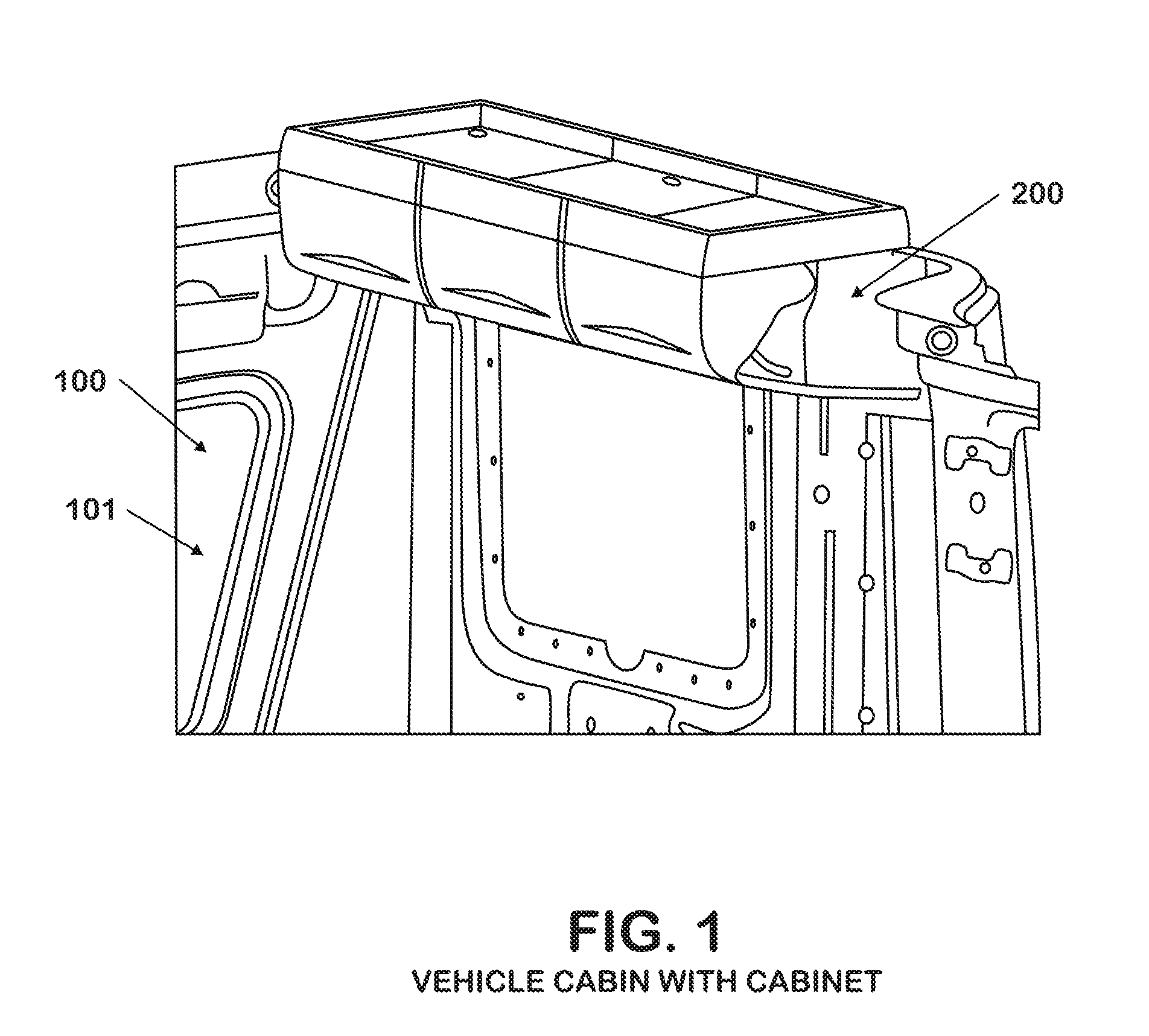
[0029]FIG. 1 shows a vehicle cabin 100 constructed of vehicle cabin sheet metal 101. A cabinet 200 is attached to the vehicle cabin sheet metal 101 by means of cleats 300 (not shown) and cleat receivers 400 (not shown).

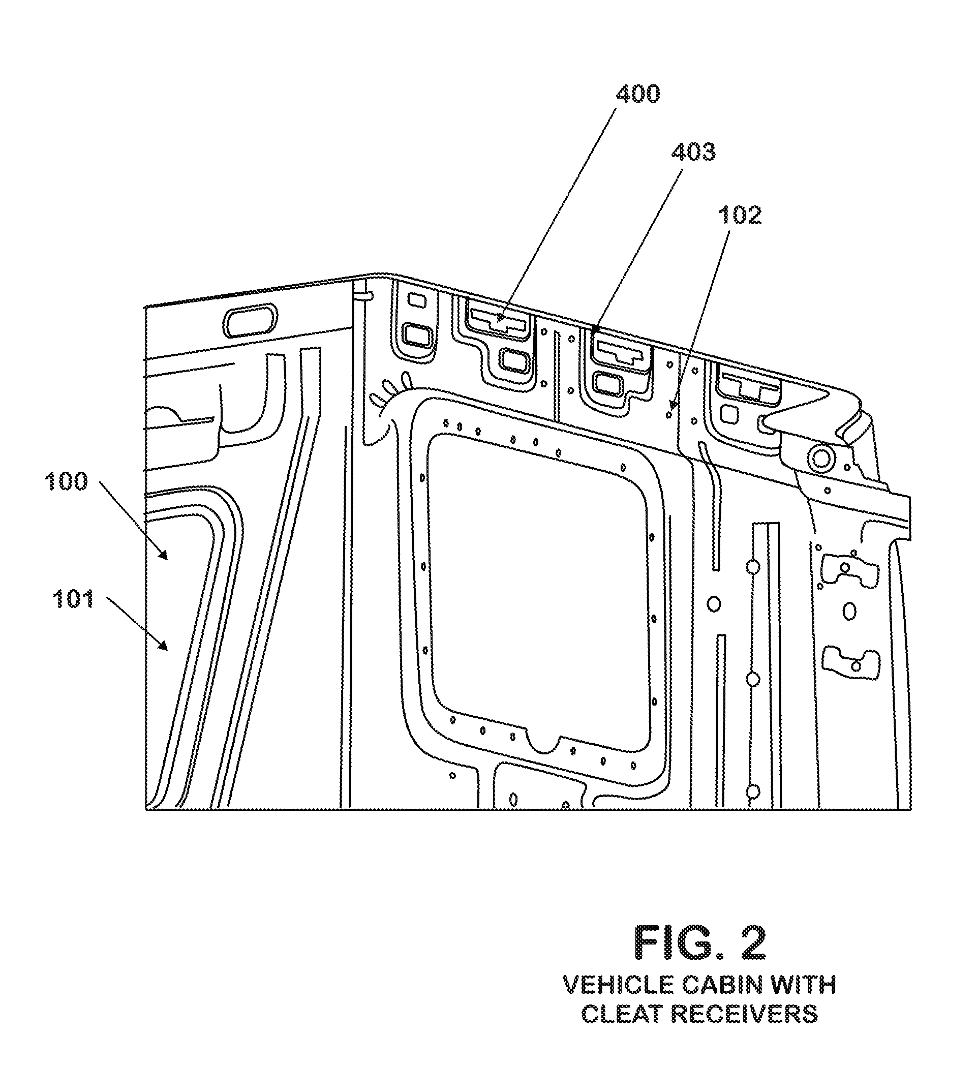
[0030]FIG. 2 again shows a vehicle cabin 100 constructed of vehicle cabin sheet metal 101. The vehicle cabin sheet metal 101 is provided with cleat receivers 400 and mounting holes 102, for the attachment of one or more cabinets 200 (not shown). The cleat receivers 400 have formed cleat receiver reinforcing material offsets 403, in order to reduce strain in the vehicle cabin sheet metal 101, and to provide firm support for the one or more cabinets 200 (not shown).

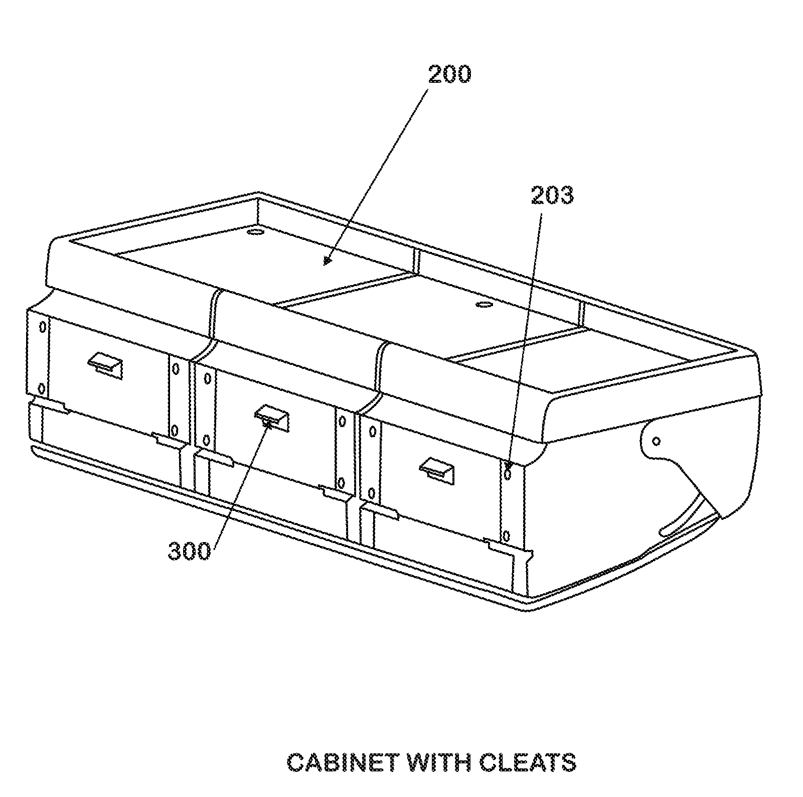
[0031]FIGS. 3 and 4 both show cabinets 200 having cleats 300 and mounting holes 203. FIG. 5 shows such a cabinet 200 installed in a vehicle cabin 100. The cleats 300 are engaged with the cleat receivers 400 which are formed from the vehicle cabin sheet metal 101. The cleat receivers 400 again have formed clea...


PUM


Abstract

A vehicle cabinet having cabinet cleats used in conjunction with a vehicle cabin having cabinet cleat receivers is provided for use with a vehicle for operation on the ground. The cabinet cleat receivers cooperate with the cabinet cleats in such a way that locating the receivers with the cleats is easy and requires minimal manipulation by an installer. It is emphasized that this abstract is provided to comply with the rules requiring an abstract that will allow a searcher or other reader to quickly ascertain the subject matter of the technical disclosure. It is submitted with the understanding that it will not be used to interpret or limit the scope or meaning of the claims.

Description

FIELD OF THE INVENTION[0001]This invention relates to the installation of heavy structures, particularly cabinets, in vehicle cabins during the process of assembly. Vehicles such as line haul trucks and recreational vehicles often are provided with cabinets for the storage of clothing, tools, food, supplies, and other articles. These cabinets are often installed in a relatively complete configuration, in order to minimize secondary operations needed to complete them on an assembly line. As a result, the cabinets are usually quite heavy at the point of installation, requiring physical strength by the line operator in order to hold them in proper alignment until they are fastened into place. Alternately, fixtures and mechanical devices are sometimes used to hold such cabinets in place until such time as they are fastened securely. A need exists for a simple, inexpensive, and effective way to rapidly install such cabinets in place without the need for fixtures or mechanical devices, an...

Claims


Application Information

Patent Timeline
IPC IPC(8): B60N3/00A47B81/00
CPCB62D33/0612B60R7/04
Inventor KITTELSON, ROBERT C.REED, JOEL D.TEMPLE, PATRICK E.SIEBERT, TIMOTHY G.KIPFER, CHARLES W.
Owner NAVISTAR CANADA
Learn More