Sliding system with onboard moving-coil linear motor

Active Publication Date: 2009-09-17
NIPPON THOMPSON
View PDF8 Cites 23 Cited by
  • Summary
  • Abstract
  • Description
  • Claims
  • Application Information

AI Technical Summary

Benefits of technology

[0014]With the sliding system in which the armature assembly is forced to move together with the table having mounted thereon with the slider, selection of any one stationary bed from beds different in length for an only moving table of a preselected length makes it possible to comply with different stroke lengths of the table according to the slider, getting the sliding system convenient for usage. The constructional feature in which the cores of magnetic material fit insider the winding turns of the armature windings contributes to high propulsion, high traveling velocity and high response of the table, less power consumption for desired propulsion. Moreover, the constructional feature that the stay integral with the cores is held together with the coil board on the side of the table contributes to making the coil board less in thickness, eventually getting overall the sliding system shrinking in height, thereby making it easier to render the bed to carry the moving table small in width. Especially, the coil board carried on the integral stay helps narrow down the interval between the field magnet arrays to allow the coil board traveling through there, making it possible to extend the traveling stroke of the table even with small in construction, eventually getting overall the sliding system shrinking in height or compact and simple in dimension. Moreover, the sliding system constructed as stated earlier has high propulsion, superior accuracy, high durability, high reliability, convenience to operate, less consumption of power and inexpensive cost in production.
[0015]Furthermore, the integral combination of every core with the stay for the armature assembly makes it possible to render the coil board of the

Problems solved by technology

The prior sliding system was then expected of longer traveling stroke of the slider than ever, with high velocity running and high response, and shrinkage in const

Method used


Image

  • Sliding system with onboard moving-coil linear motor
  • Sliding system with onboard moving-coil linear motor
  • Sliding system with onboard moving-coil linear motor

Examples


Embodiment Construction

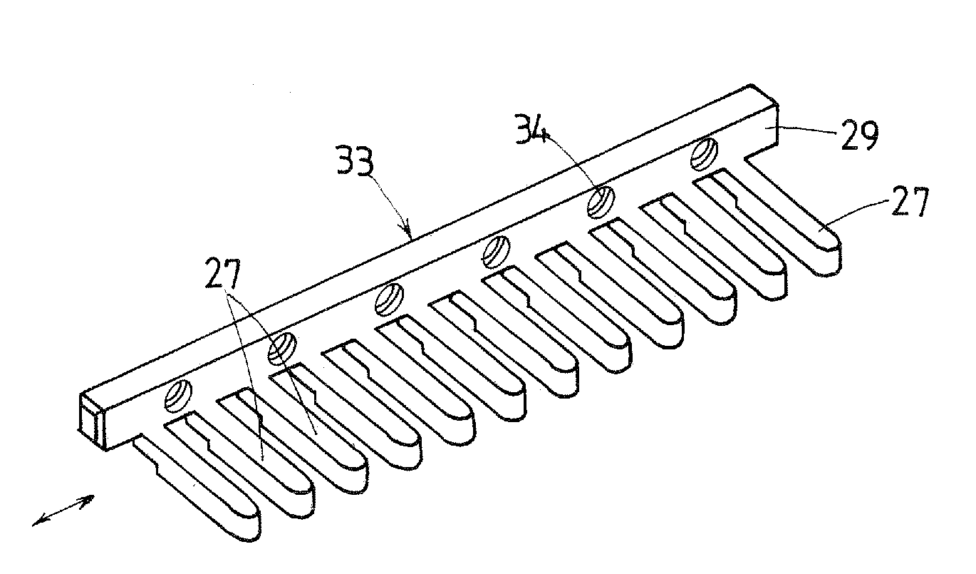
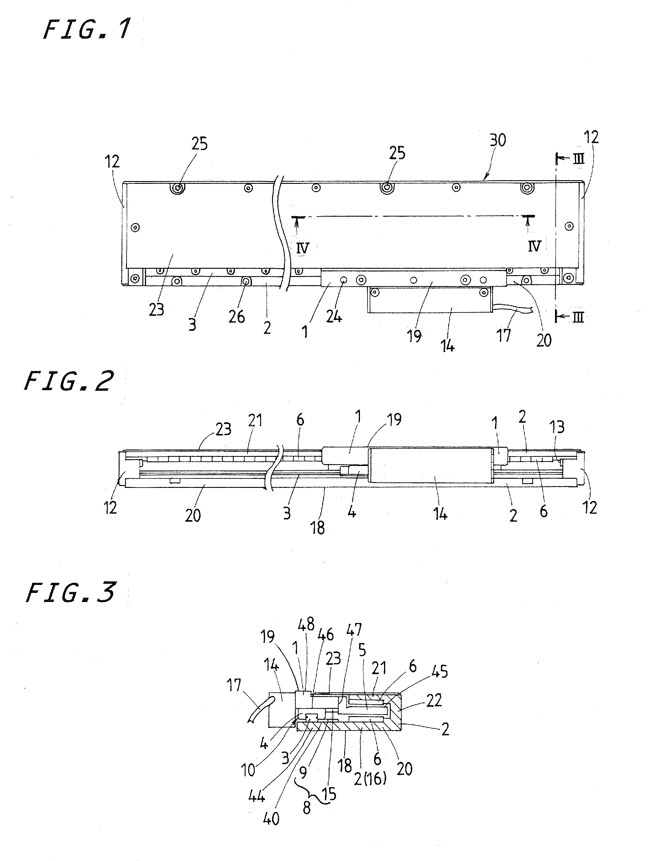
[0027]Preferred embodiments of a sliding system according to the present invention will be explained hereinafter in detail with reference to the accompanying drawings. The sliding system with an onboard moving-coil linear motor is envisaged incorporating it in a diversity of machinery including semiconductor manufacturing equipments, various assembling machines, measuring / inspection equipments, testing machines, machine tools, testing instruments, position-control system, sliding table system, and so on. Selection of any one stationary bed from beds different in length for an only moving table of a preselected length as shown in FIGS. 1 to 3 makes it possible to comply with different stroke lengths of, for example 120 mm˜300 mm, getting the sliding system convenient for usage.

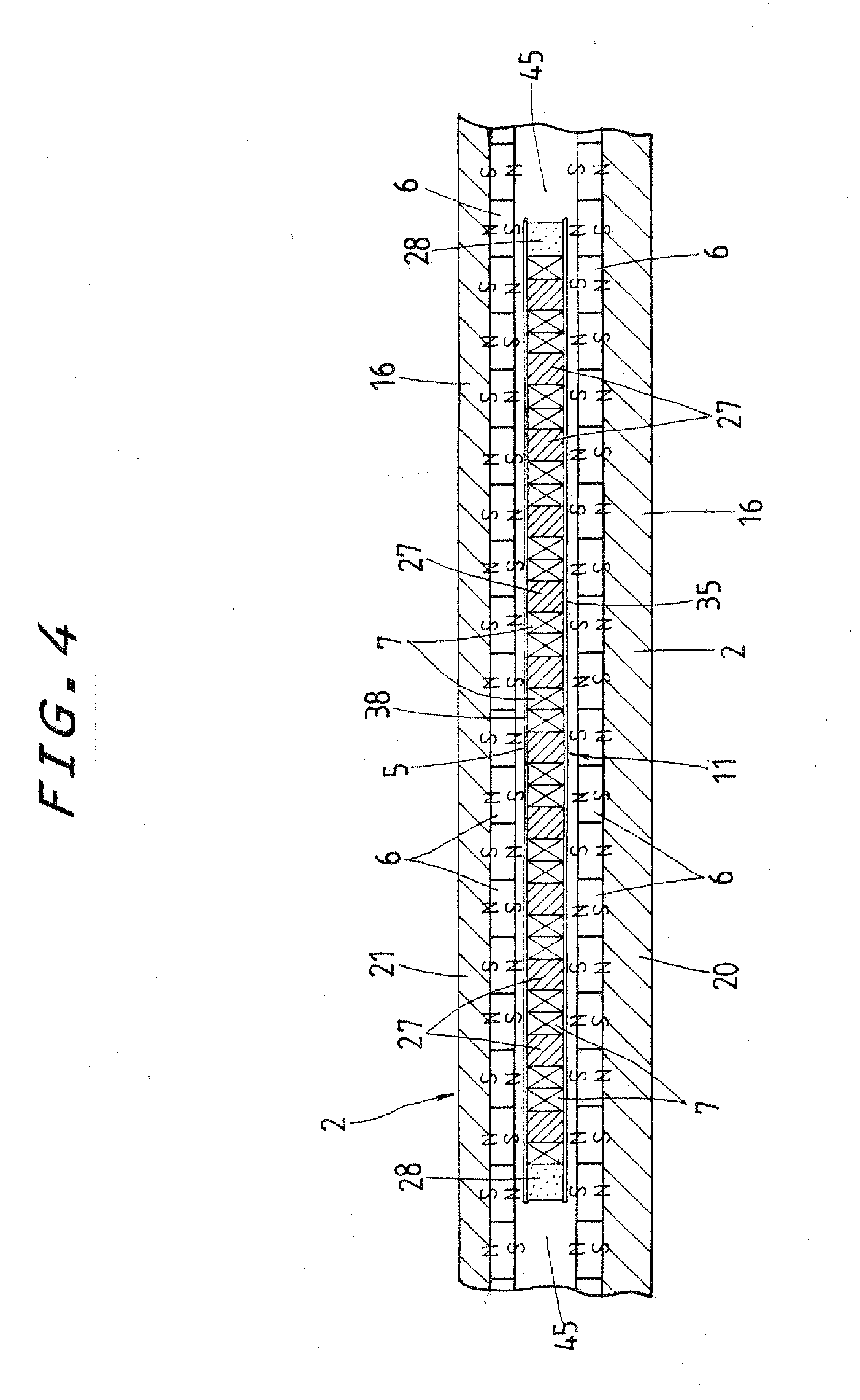
[0028]A sliding system 30 of the present invention as shown in FIGS. 1 to 4 is constituted with an elongated bed 2 to provide an integral magnet yoke 16 which has an angled configuration like a hook in a transv...


PUM


Abstract

A sliding system with onboard moving-coil linear motor is disclosed in which an armature assembly is a printed-circuit board, armature windings of flat configuration and coil stay having a stay and any number of cores made integral with the stay. The armature assembly is held by virtue of the stay at a preselected location inside an interval defined between field magnet arrays and, therefore, is small and compact in height in transverse section. A bed formed in an angled hook-like configuration in a transverse section contributes to shrinkage of the sliding system in either of height and width in transverse section or most compactness of the sliding system in transverse dimension. Moreover, the bed can be selected in length at discretion according to the purpose of usage to provide any desirable stroke length for a single table of a preselected length, getting the sliding system convenient for usage.

Description

FIELD OF THE INVENTION[0001]The present invention relates to a sliding system with onboard moving-coil linear motor, which is adapted to be used in fields as diverse as semiconductor industries, various assembling machines, precise measuring / inspection equipments, testing machines, machine tools, and so on.BACKGROUND OF THE INVENTION[0002]Recent sliding systems with onboard linear motor are finding extensively increased applications in various machines including semiconductor industries, various assembling machines, precise measuring / inspection equipments, testing machines, machine tools, and so on. The sliding systems are needed to be shrinking in size, compact and simple in construction, and yet having high propulsion, superior accuracy, high durability, high reliability, convenience to operate, less consumption of power and inexpensive cost in production. Moreover, the linear motion guide units having mounted with the sliding system constructed as stated earlier require maintenan...

Claims


Application Information

Patent Timeline
IPC IPC(8): H02K41/03
CPCH02K1/14H02K41/03H02K3/47
Inventor IDA, EIJISASAKI, SATOSHI
Owner NIPPON THOMPSON
Why Eureka
Try Eureka