System for applying optical forces from phase gradients

a technology of optical forces and gradients, applied in the field of systems for applying optical forces from phase gradients, can solve the problems of limiting the types and efficiency of forces and manipulations that can be used for demanding commercial applications, and the degree of freedom of optical tweezers, so as to achieve the effect of flexible and useful use and flexibl

Inactive Publication Date: 2009-09-17
NEW YORK UNIV
View PDF1 Cites 10 Cited by
  • Summary
  • Abstract
  • Description
  • Claims
  • Application Information

AI Technical Summary

Benefits of technology

[0004]A method and system have been developed for a new category of optical force by using phrase gradients in place of, or in concert with, light intensity gradients. This new category of optical force enables redirection of electromagnetic radiation pressure to create optical forces transverse to an optical axis. This new type of optical force can be used alone or in combination with

Problems solved by technology

However, optical tweezers do have substantial limitations on the degrees of freedom that can be created, thereby li

Method used


Image

  • System for applying optical forces from phase gradients
  • System for applying optical forces from phase gradients
  • System for applying optical forces from phase gradients

Examples


Embodiment Construction

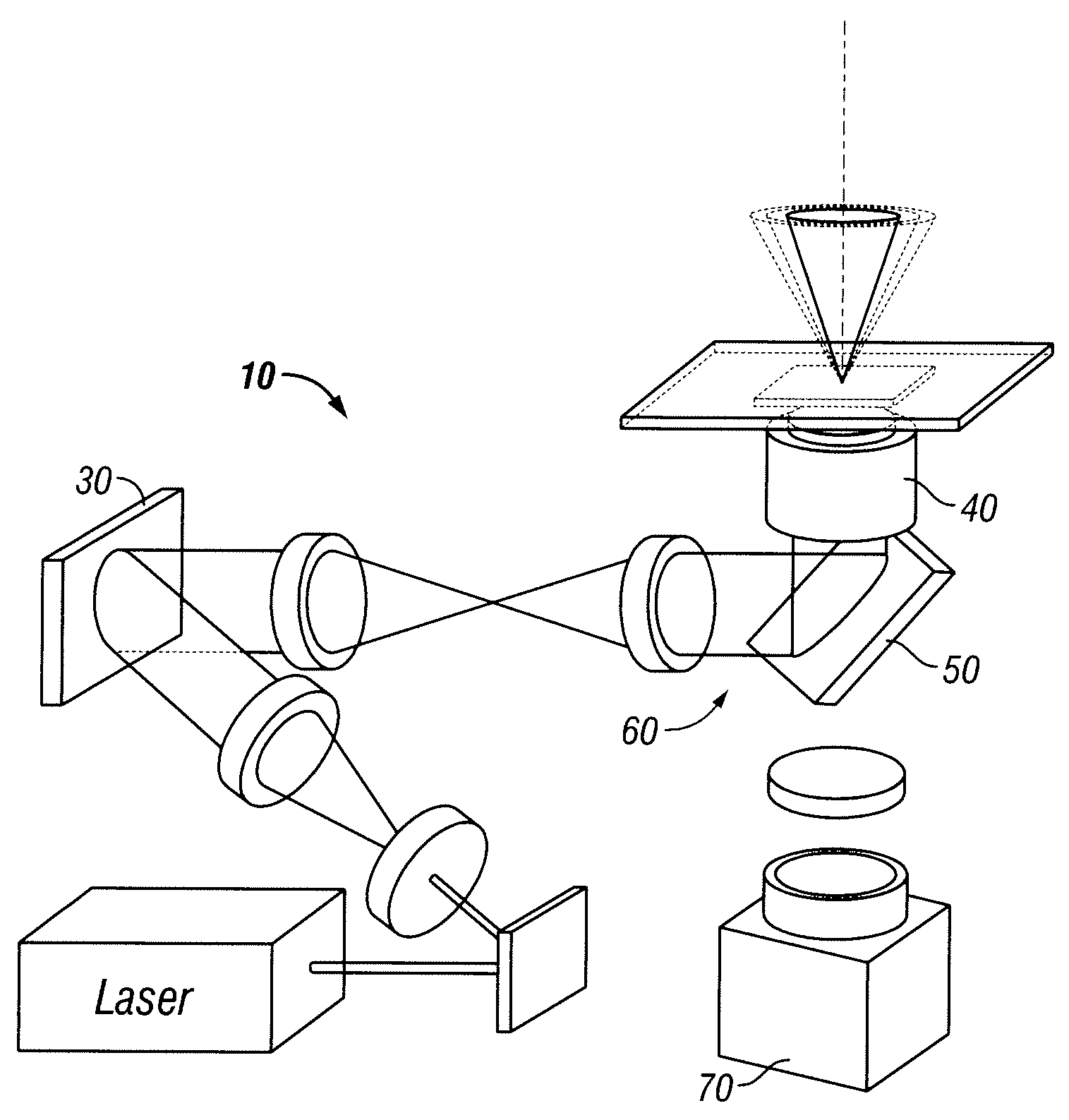
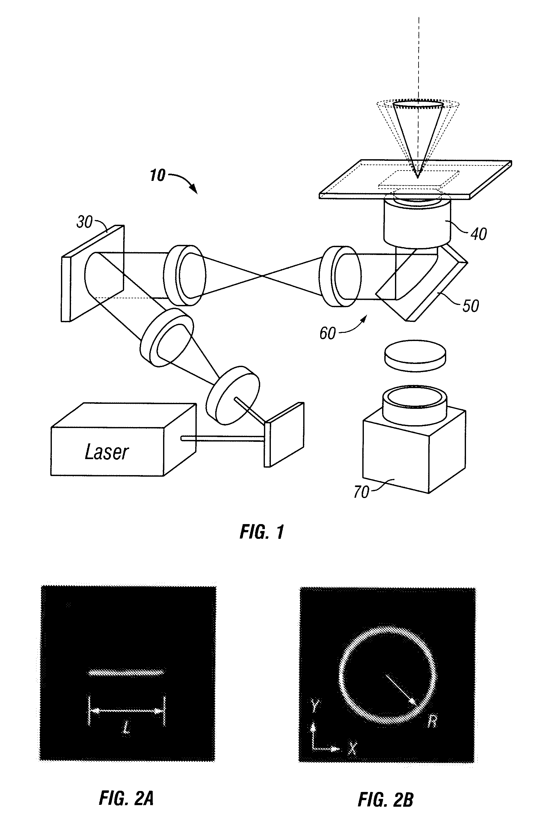
[0011]A holographic optical trapping system for performing shape phase holography is shown at 10 in FIG. 1. This system 10 can create optical traps with phase gradients transverse to the optical axis 20, as well as provide optical tweezers created by intensity gradients.

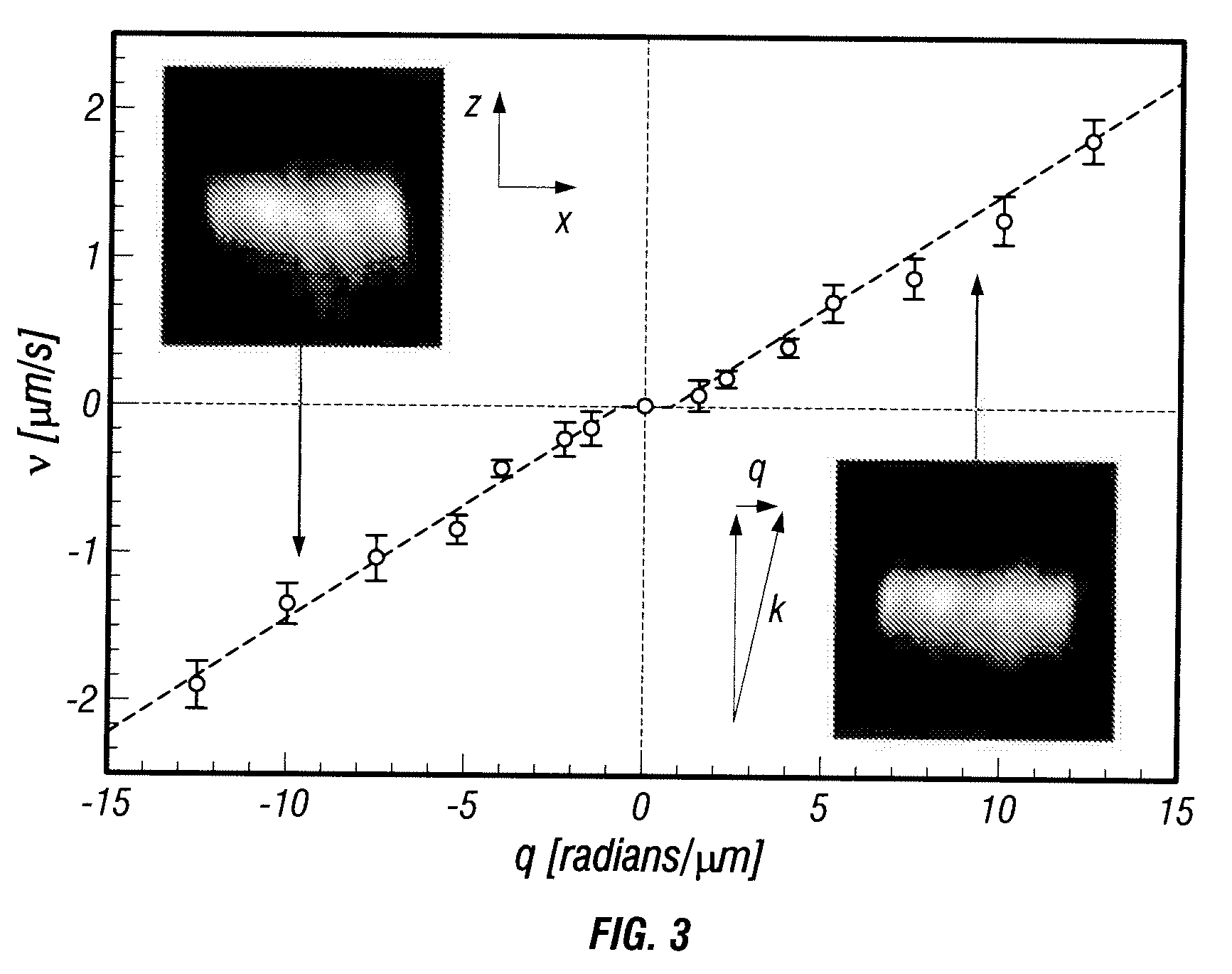
[0012]The phase gradients generated by the method described herein can redirect radiation pressure to create optical force fields transverse to the optical axis 20. Photon orbital angular momentum (OAM) is one experimentally realized example of this phenomenon. Phase-gradient forces can be applied by combining them with intensity gradients in holographically projected light fields to create a new category of extended optical traps with tailored force profiles.

[0013]The vector potential describing a beam of light of frequency ω and polarization {circumflex over (ε)}(r) can be written as

A(r,t)=u(r)eiΦ(r)e−ωt{circumflex over (ε)}(r)  (1)

where u(r) is the real-valued amplitude and Φ(r) is the real-valued phase. We assume...


PUM


Abstract

A system and method for creating extended optical traps for applying optical forces to a material to be manipulated for a commercial application. The system and method include applying a hologram of appropriate characteristics to a beam of light wherein the hologram characteristics include a transverse optical component to apply optical forces transverse to an optical axis of the system. A shape phase component achieves this transverse optical component and also intensity gradient components can be applied via the hologram to provide programmable extended optical traps for a selectable commercial application.

Description

[0001]The United States Government has certain rights in this invention pursuant to a grant from the National Service Foundation through Grant Number DMR-0606415.[0002]This invention is directed toward a system and method for applying optical forces by use of phase gradients. More particularly, the system and method employs phase gradients in a light field to create a new category of optical traps which provide additional features compared to conventional intensity gradient traps (optical tweezers).BACKGROUND OF THE INVENTION[0003]Optical tweezers have demonstrated substantial value in various commercial applications, such as for example, separation of particles of different characteristics and dynamic manipulation of small objects for numerous, commercial, manufacturing and processing applications. However, optical tweezers do have substantial limitations on the degrees of freedom that can be created, thereby limiting the types and efficiency of forces and manipulations that can be...

Claims


Application Information

Patent Timeline
IPC IPC(8): G02B5/32
CPCG03H1/0005G03H1/22G03H2210/10G03H2001/0077G03H2001/085G03H1/2294
Inventor ROICHMAN, YOHAISUN, BOROICHMAN, YAELAMATO-GRILL, JESSEGRIER, DAVID G.
Owner NEW YORK UNIV
Why Eureka
Try Eureka