Developer supply device, developer supply control method, and developer supply control program

a technology of developer supply and supply control, applied in the field of image forming devices, can solve problems such as reducing device productivity, and achieve the effect of preventing the stop of printing operation and reducing the image density on the occasion of continuous printing

Inactive Publication Date: 2009-09-17
PANASONIC CORP
View PDF12 Cites 19 Cited by
  • Summary
  • Abstract
  • Description
  • Claims
  • Application Information

AI Technical Summary

Benefits of technology

[0017]In the present invention, since the adoption of this configuration enables the supplement of the consumed toner within the development device in an appropriate timing during printing of an image on one page, the fluctuation in the toner concentration during the printing of the image on one page...

Problems solved by technology

Further, for the purpose of preventing this decrease, when the number of pixels of the printed image is detected and an image with the large number of pixels is printed, if the consumed toner is attempted to be supplemented before print...

Method used


Image

  • Developer supply device, developer supply control method, and developer supply control program
  • Developer supply device, developer supply control method, and developer supply control program
  • Developer supply device, developer supply control method, and developer supply control program

Examples


embodiment 1

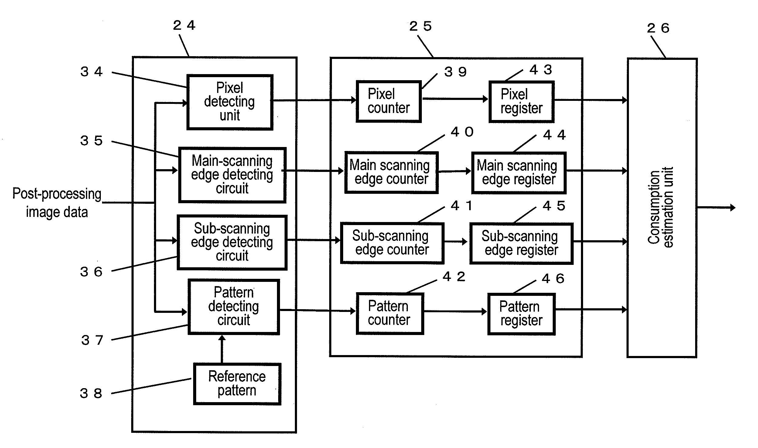
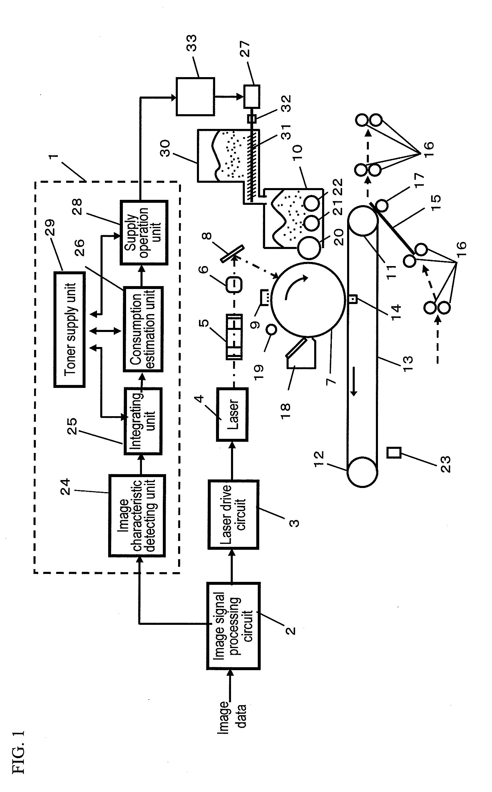
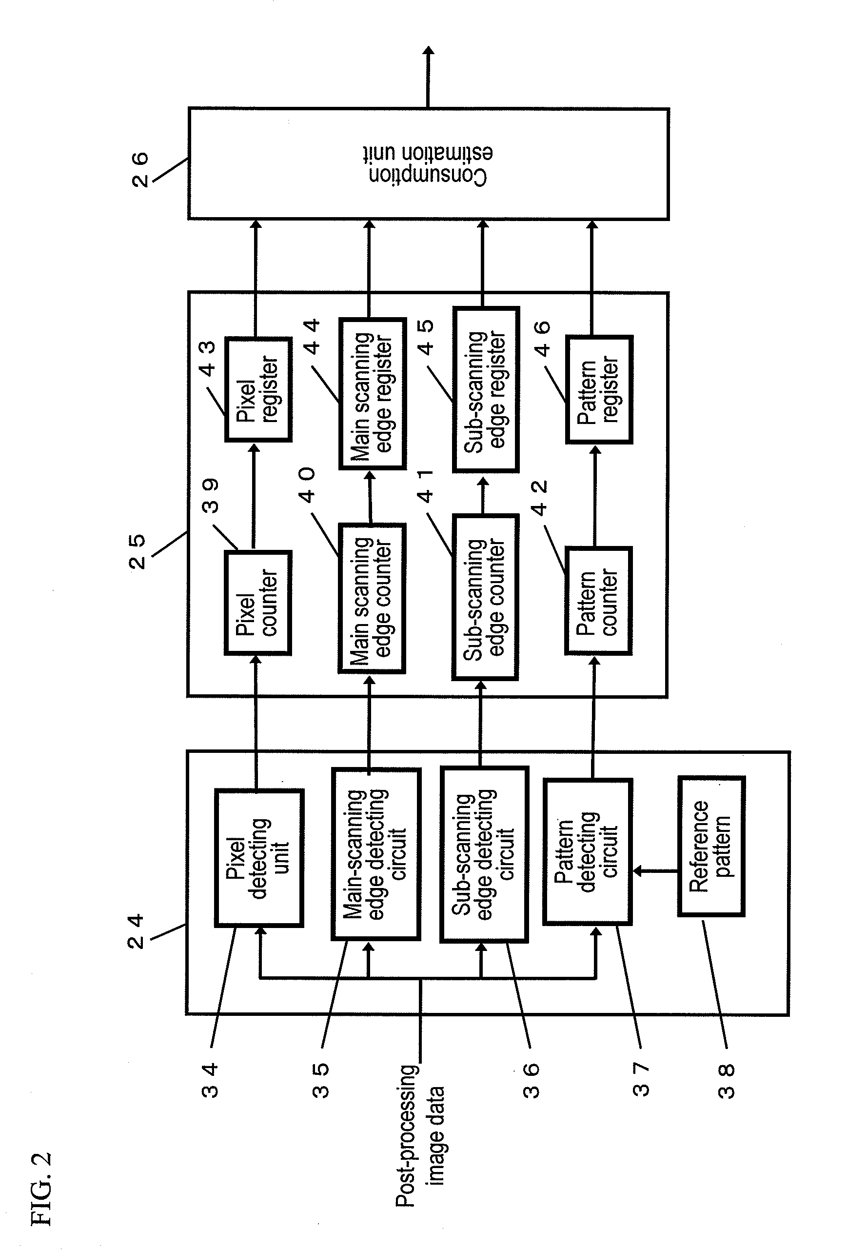
[0070]FIG. 1 shows a skeleton framework of an image forming device (referred to as this device) comprising a developer supply device and having a document copying function, as Embodiment 1 relating to the present invention.

[0071]In FIG. 1, this image forming device is roughly composed of an image signal processing unit for processing input image data, a laser optical system unit for guiding a light generated for the purpose of exposing a photoreceptor based upon image data processed by the image signal processing unit, an image forming unit for forming a visible image via an electrophotographic process, a toner supply mechanism unit, which is a developer supply device relating to the present invention for supplying a toner to a development device of the image forming unit, and a toner concentration control unit 1 for controlling the toner supply mechanism unit.

[0072]Each component is further constructed as described below.

[0073]The image signal processing unit is composed of an imag...

embodiment 2

[0176]Next, Embodiment 2 of the present invention will be described.

[0177]In this embodiment, the image forming device (referred to as this device) 1 has the configuration of the image forming device, and the toner concentration controlling unit 1 further comprises a toner consumption database to images printed by this device.

[0178]FIG. 9 shows a skeleton framework of the image forming device in this embodiment.

[0179]In FIG. 9, a toner consumption database 61 stores the history of toner consumption per page, and this device sequentially calculates an average value of the toner consumption (referred to as average toner consumption) from the beginning and an average value of the toner consumption of latest five pages (referred to as latest toner consumption) every time the printing operation is conducted.

[0180]The electrographic image forming process is the same as that in Embodiment 1.

[0181]Hereafter, the operation of the image forming device with this configuration will be described...


PUM


Abstract

An image forming device in which the toner density of a two-component developing device can be stably controlled in printing a one-page image and the frequency of interruption of even printing a series of pages can be decreased as less as possible. The number of pixels of the image relevant to the development counted during the printing and the toner consumption is estimated from other image information, and the amount of toner corresponding to the consumption is supplemented. In this supplement, the count is acquired at an intermediate time of the one-page printing, the toner consumption is estimated, and the toner is supplemented during the printing after the intermediate time. Thereby, toner supplement can be performed ahead of its schedule, and a variation of the toner density can be prevented correspondingly.

Description

TECHNICAL FIELD[0001]The present invention relates to an image forming device, such as a copier or a printer, using a developer. In particular, the present invention relates to a technology where a consumed toner is supplemented to a development device (said supplement to a development device also referred to as a ‘supply’) and the toner concentration (a ratio of the toner in a two-component developer) within the development device is controlled at a standard within a predetermined range with regard to the development device that makes an electrostatic latent image formed on an image supported body, such as a photoreceptor, visible using a two-component developer composed of a toner and a magnetic carrier (hereafter, simply referred to as ‘carrier’).BACKGROUND ART[0002]In an electrophotographic device (an image forming device using an electrophotographic method) using a two-component developer composed of a toner and a carrier, a mixture ratio affects an output image (an image forme...

Claims


Application Information

Patent Timeline
IPC IPC(8): G03G15/08
CPCG03G2215/0685G03G2215/0888G03G15/5058G03G15/0849G03G15/0877
Inventor TAKAHASHI, NAOKIHAYASHI, KAZUMASA
Owner PANASONIC CORP
Why Eureka
Try Eureka