Energy storage device and method
a technology of energy storage and energy storage, which is applied in the direction of non-aqueous electrolyte accumulator electrodes, cell components, electrical apparatuses, etc., can solve the problems of beta alumina separator electrode damage, associated performance degradation,
- Summary
- Abstract
- Description
- Claims
- Application Information
AI Technical Summary
Benefits of technology
Problems solved by technology
Method used
Image
Examples
example 1
Preparation of Electrode
[0097]Several metal-coated carbon foam electrodes, measuring 1.25 cm×1.25 cm×2 mm thick, are prepared by electroplating foamed carbon with a copper layer or a nickel layer, as appropriate. The carbon foam is obtainable from ERG Materials and Aerospace Corp. (Oakland, Calif.). The foam electrodes have a carbonaceous skeleton of reticulated vitreous carbon (RVC) foam. The carbon foam pore density is 100 pores per inch (PPI) and the pore diameter is about 100 micrometers on average.
[0098]The electroplating is performed in an aqueous copper or nickel solution, as appropriate. The plating encapsulates the carbon foam to form the prepared metal-coated porous electrode substrates. Several of the nickel-coated porous electrodes are further submersed in a zinc solution and zinc metal is plated onto the nickel layer.
[0099]The finished metal-coated carbon foam electrodes are analyzed and characterized. The surface of the copper-coated electrode substrates appears smooth...
example 2
Preparation of a Separator
[0100]A plurality of separators are prepared. The plurality includes two groups of separators, each having a differing stabilizer phase type. The two different zirconia phase types include (i) 8 mol. % Y2O3 stabilized cubic phase zirconia (8YSZ) and (ii) 4.5 mol. % Y2O3 stabilized tetragonal and cubic phase zirconia (4.5YSZ).
[0101]The separators formed using the stabilized zirconia are formed as three types of discs. The three types of discs include two types of (i), and one type of (ii). The three samples sets are characterized as having compositions of: (a) 50 vol. % alpha-alumina+50 vol. % 8 YSZ; (b) 70 vol. %.alpha-alumina+30 vol. % 8 YSZ; and (c) 50 vol. % alpha-alumina+50 vol. % 4.5 YSZ. Disc-shaped samples of 2.5 millimeters (mm) thickness of compositions (a), (b), and (c) are fabricated using requisite powder mixtures, die-pressing, followed by isostatic pressing, and then sintering in air at 1600 degrees Celsius. The sintered discs are placed in a ...
example 3
Formation of a Test Cell, and Testing Thereof
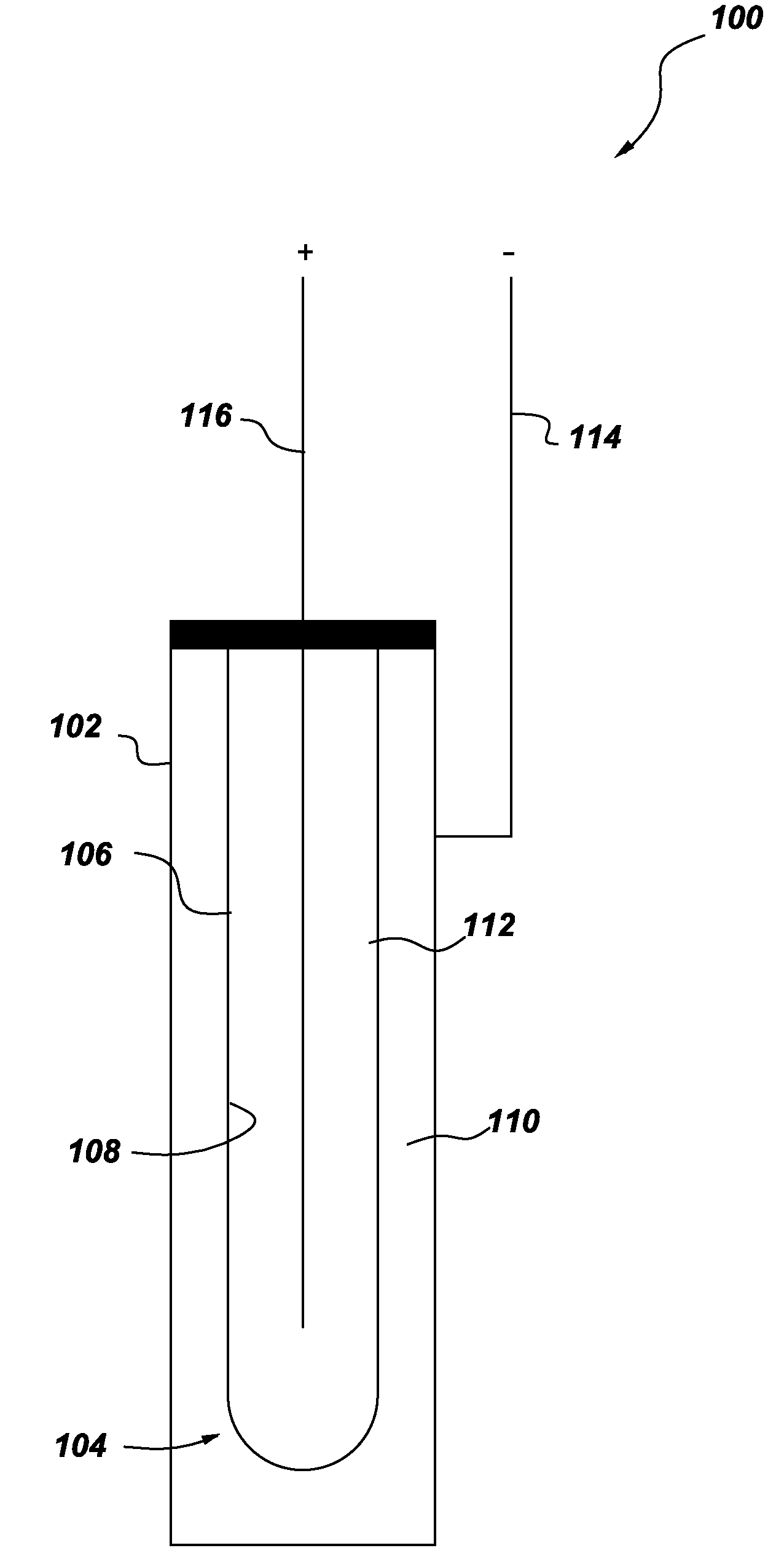
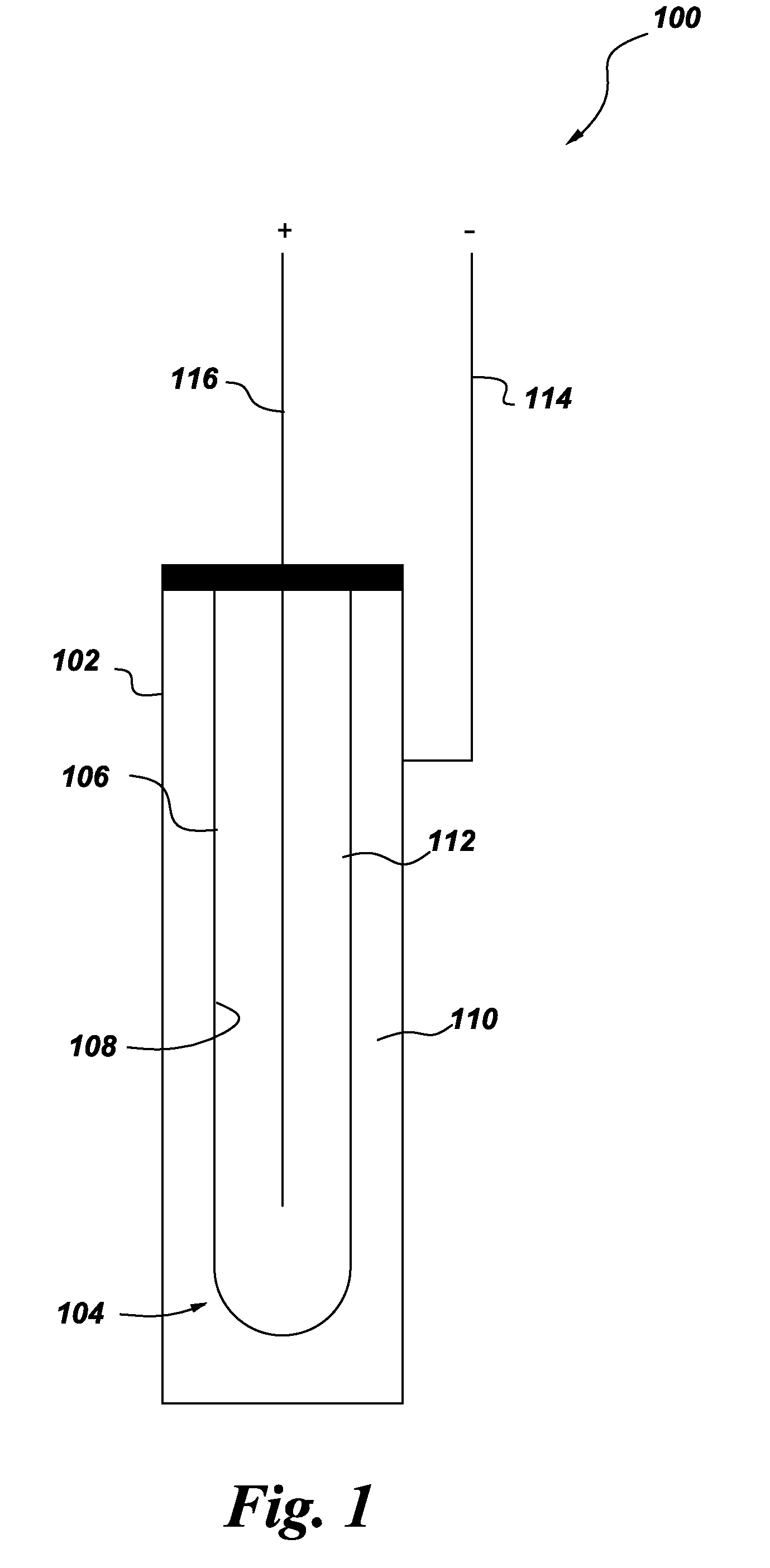
[0103]The cell configuration for the test in Example 3 is substantially the same as the schematic configuration shown in FIG. 1. A composite separator tube, cylindrical in shape, is formed according to the process of Example 2 using composition (a). The cylinder dimensions are 228 mm length, 36 mm internal diameter, and 38 mm outside diameter. The composite separator tube is glass sealed to an alpha alumina collar. The assembly is placed in a stainless steel can. The can size is about 38 mm×38 mm×230 mm. The composite separator contains 50 grams (g) Cu, 22 grams NaCl, and 25 grams NaAlCl4. In addition, 11 grams of reticulated vitreous carbon is added to the cathode to prevent settling of CuCl between charge and discharge. An electric heater surrounds the cell. During operation, the cell is heated to the operating temperature of 300 degrees Celsius. The cell is charged and discharged at currents of 4 amps and of 12 amps. After a few cycles...
PUM
| Property | Measurement | Unit |
|---|---|---|
| operating temperature | aaaaa | aaaaa |
| reduction potential | aaaaa | aaaaa |
| melting point | aaaaa | aaaaa |
Abstract
Description
Claims
Application Information
 - R&D
- Intellectual Property
- Life Sciences
- Materials
- Tech Scout
- Unparalleled Data Quality
- Higher Quality Content
- 60% Fewer Hallucinations
Browse by: Latest US Patents, China's latest patents, Technical Efficacy Thesaurus, Application Domain, Technology Topic, Popular Technical Reports.
© 2025 PatSnap. All rights reserved.Legal|Privacy policy|Modern Slavery Act Transparency Statement|Sitemap|About US| Contact US: help@patsnap.com


