Substrate mounting table, substrate processing apparatus and temperature control method

a technology for processing apparatus and substrates, applied in electrical equipment, basic electric elements, electric discharge tubes, etc., can solve the problems of difficult to maintain the whole surface of the wafer at a uniform temperature, difficult to uniformly and difficult to control the temperature of the wafer as desired

Inactive Publication Date: 2009-09-17
TOKYO ELECTRON LTD
View PDF6 Cites 23 Cited by
  • Summary
  • Abstract
  • Description
  • Claims
  • Application Information

AI Technical Summary

Benefits of technology

[0037]In accordance with the present invention, it is possible to provide a substrate mounting table capable of controlling the ratio of heat dissipation amounts in the peripheral region and central region of a substrate and free from an abnormality such as an abrupt change in the heat dissipation amount in a local area of the substrate or the like, a substrate processing apparatus incorporating the substrate mounting table and a substrate temperature control method.
[0038]Furthermore, use of the present substrate mounting table makes it possible to generate a desired gas pressure difference in the mounting table with a minimum necessary amount of heat transfer gas (helium, etc.). Consequently, it is possible to control the whole substrate at a desired uniform temperature.

Problems solved by technology

As a result, a problem is posed in that it becomes difficult to uniformly control the temperature of the wafer.
This poses a problem in that it becomes difficult to control the temperature of the wafer as desired.
This leads to a problem in that it is difficult to maintain the whole surface of the wafer at a uniform temperature.
In general, the center of the wafer is easy to cool but the periphery thereof is cooled insufficiently.
This is problematic in that an abnormality may appear in the substrate properties.

Method used


Image

  • Substrate mounting table, substrate processing apparatus and temperature control method
  • Substrate mounting table, substrate processing apparatus and temperature control method
  • Substrate mounting table, substrate processing apparatus and temperature control method

Examples


first embodiment

[0049]Hereinafter, the present invention will be described with reference to the accompanying drawings.

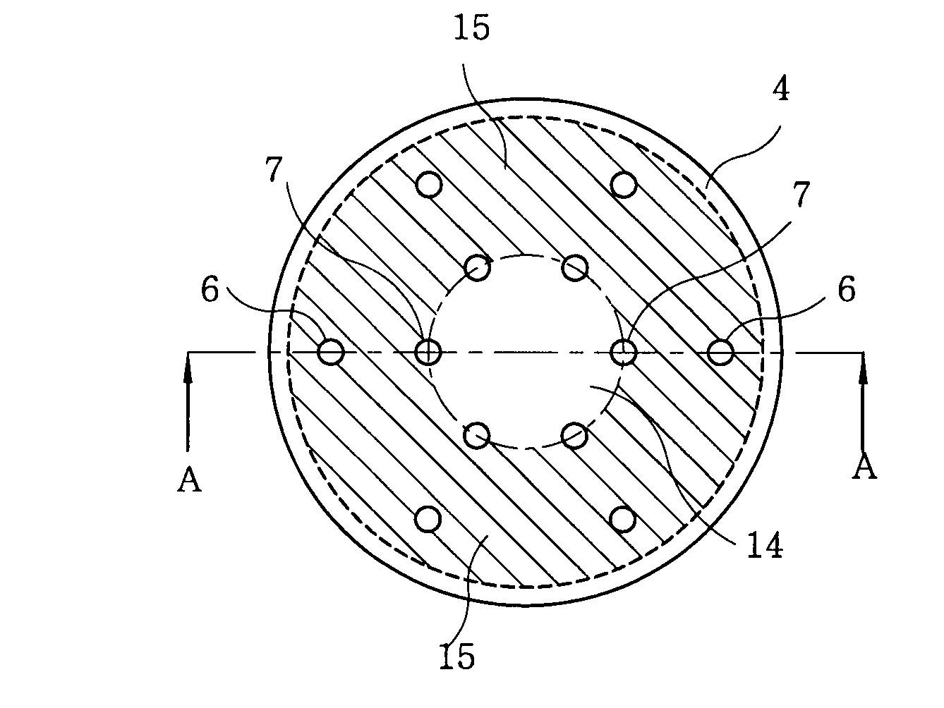
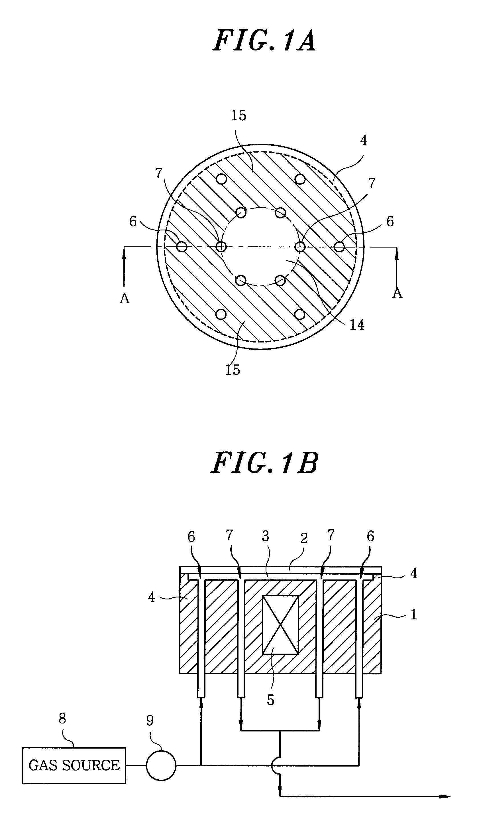
[0050]FIG. 1A is a plan view showing a substrate mounting table in accordance with the first embodiment of the present invention and FIG. 1B is a section view taken along line A-A in FIG. 1A.

[0051]A substrate (wafer) 2 to be processed is mounted on the upper portion of a mounting table 1. A depressed portion is formed in a substrate mounting surface, i.e., the surface of the mounting table 1 on which the substrate is mounted. A gap 3 is formed between the substrate mounting surface and the substrate 2.

[0052]An annular peripheral ridge portion 4 is provided along the outer periphery of the depressed portion. The peripheral ridge portion 4 serves to support the peripheral edge of the substrate 2 and also to prevent leakage of a heat transfer gas from the gap 3. The gap 3 becomes a closed space due to the presence of the peripheral ridge portion 4.

[0053]A plurality of protrusions (not...

second embodiment

[0098]FIGS. 8A, 8B and 8C are views showing a substrate mounting table in accordance with the present invention. FIG. 8A is a plan view of the substrate mounting table (illustrating the left half thereof), FIG. 8B is a section view taken along line B-B in FIG. 8A, and FIG. 8C is an enlarged view of the portion designated by C in FIG. 8B.

[0099]In the second embodiment, a substrate 2 is mounted on an annular peripheral ridge portion 4 of a mounting table 1. A gap 3 through which a heat transfer gas flows is formed between the surface of the mounting table 1 and the substrate 2. A heat transfer gas inlet port 6 is formed near the peripheral edge of the mounting table 1 and a heat transfer gas outlet port 7 is formed in the central region of the mounting table 1, as is the case in the first embodiment shown in FIG. 1.

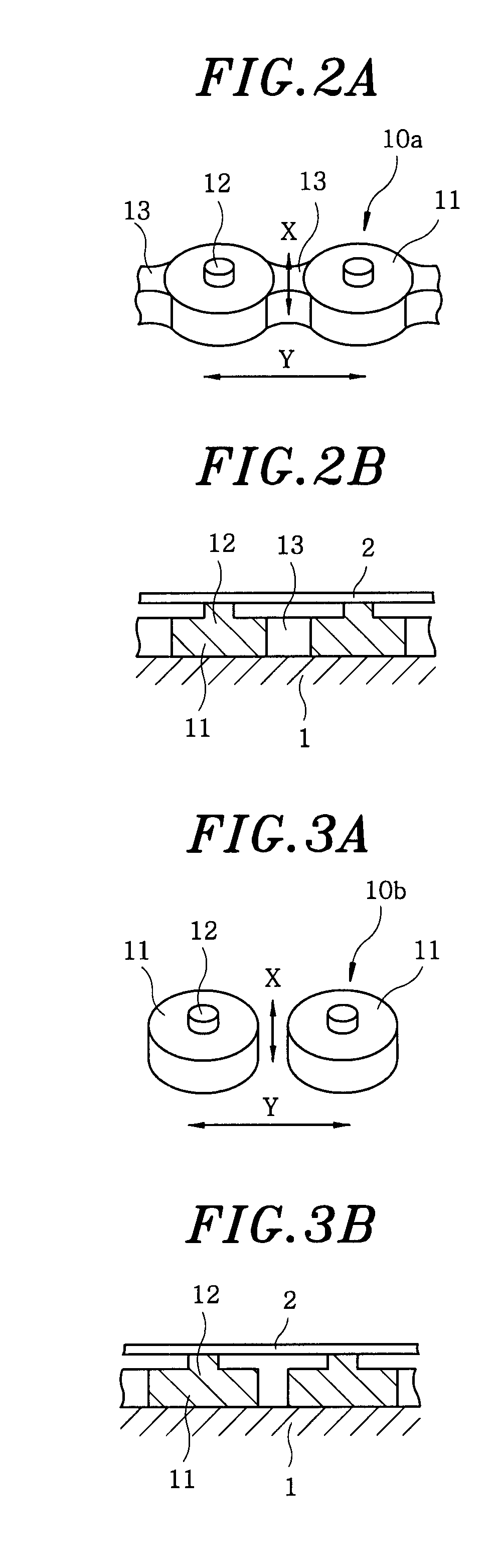
[0100]The second embodiment differs from the first embodiment in that, in place of the connection type or non-connection type dot-like projection 10a or 10b shown in FIG. 2...

third embodiment

[0112]FIGS. 9A and 9B are views showing a substrate mounting table in accordance with the present invention. FIG. 9A is a plan view of the substrate mounting table (on which no substrate is mounted) and FIG. 9B is a section view taken along line C-C in FIG. 9A.

[0113]In the peripheral edge of a mounting table 1, there is provided an annular peripheral ridge portion 4 on which a substrate is mounted. Just like the preceding embodiments, a heat transfer gas inlet port 6 is formed near the peripheral edge of the mounting table 1 and a heat transfer gas outlet port 7 is formed in the central region of the mounting table 1.

[0114]In the present embodiment, three generally circular partition walls 21a to 21c are concentrically provided on the upper surface of the mounting table 1. The upper surfaces of the partition walls 21a to 21c make contact with the substrate without leaving any gap between the substrate and the partition walls 21a to 21c. Therefore, the heat transfer gas is kept from ...


PUM

PropertyMeasurementUnit
pressureaaaaaaaaaa
heightaaaaaaaaaa
conductanceaaaaaaaaaa

Abstract

A substrate mounting table for mounting a substrate in a substrate processing apparatus, includes a table body having a substrate mounting surface. An annular peripheral ridge portion is formed on the substrate mounting surface of the table body. The annular peripheral ridge portion makes contact with a peripheral edge portion of the substrate and forms a closed space for circulation of a heat transfer gas below the substrate, when the substrate is mounted on the substrate mounting surface of the table body. The table body has a heat transfer gas inlet port formed in a peripheral edge region of the substrate mounting surface, a heat transfer gas outlet port formed in a central region of the substrate mounting surface, and a flow path formed on the substrate mounting surface for forming a conductance C when the heat transfer gas flows from the inlet port to the outlet port.

Description

FIELD OF THE INVENTION[0001]The present invention relates to a substrate mounting table for mounting thereon a substrate such as a semiconductor wafer or the like, a substrate processing apparatus for performing processes such as etching and the like on a substrate mounted on the substrate mounting table, and a temperature control method for controlling the temperature of a substrate mounted on the substrate mounting table.BACKGROUND OF THE INVENTION[0002]In a plasma etching process, a mounting table for mounting thereon a semiconductor wafer (hereinafter, merely referred to as “wafer” or “substrate”) to be processed is provided within a chamber. The wafer is electrostatically attracted and kept in place by means of an electrostatic chuck forming an upper portion of the mounting table. The wafer is subjected to plasma etching by generating plasma of a processing gas.[0003]Since the wafer is heated from above in such a plasma processing apparatus, a coolant flow path is provided insi...

Claims


Application Information

Patent Timeline
Patent Type & Authority Applications(United States)
IPC IPC(8): H01L21/302
CPCH01J2237/2001H01L21/68H01L21/67109H01L21/3065
Inventor SASAKI, YASUHARU
Owner TOKYO ELECTRON LTD
Why Eureka
Try Eureka