Kitchen Hood Vent and Scrubber

Inactive Publication Date: 2009-09-24
BROOKMAN DAVID L
View PDF48 Cites 15 Cited by
  • Summary
  • Abstract
  • Description
  • Claims
  • Application Information

AI Technical Summary

Benefits of technology

[0015]A fifth object of the invention is cleaning contaminated air by passing the contaminated air through a scrub reservoir containing a mixture of water and a surfactant, the scrub reservoir having a plurality of apertures in a lower surface, the contaminated air passing through the scrub reservoir apertures and forming jets for increased interaction of the water and surfactant, thereby resulting in improved efficiency in removal of the contaminates, with the addition of surfactant to the water resulting in a reduced pressure drop across the scrub reservoir.
[0016]A combination kitchen hood air cleaner and scrubber/degreaser accepts contaminated air containing contaminates such as oils and animal fats in vapor or aerosol form, and particulates such as smoke from a lower surface air inlet, thereafter increases the contaminated air velocity using a reduced area aperture to ensure positive intake, and directs the contaminated air through a pre-wet section which introduces droplets of cleaning fluid into the contaminated air stream, which is thereafter directed to the bottom surface of a scrub reservoir containing apertures, and the introduction of cleaning fluid into the contaminated air stream reduces the buildup of contamination in and around the apertures. The cleaning fluid is stored in, and pumped fluid drains back to, a main reservoir which contains the cleaning fluid such as water mixed with a non-foaming surfactant, or alternatively, the cleaning fluid can be any soluble solution for the contaminates to be removed from the contaminated air. The stream of contaminated air with cleaning fluid droplets is directed upward through apertures on the bottom surface of the scrub reservoir containing the cleaning fluid. Contaminated air which passes through the apertures of the scrub reservoir form jets through the cleaning fluid, the jets maximizing the interaction between the contaminated air and the cleaning fluid. Most of th

Problems solved by technology

This results in a large increase in the exposed surface contact between the streams of contaminated air and the flowing bed of liquid in the scrub reservoir, w

Method used


Image

  • Kitchen Hood Vent and Scrubber
  • Kitchen Hood Vent and Scrubber
  • Kitchen Hood Vent and Scrubber

Examples


Embodiment Construction

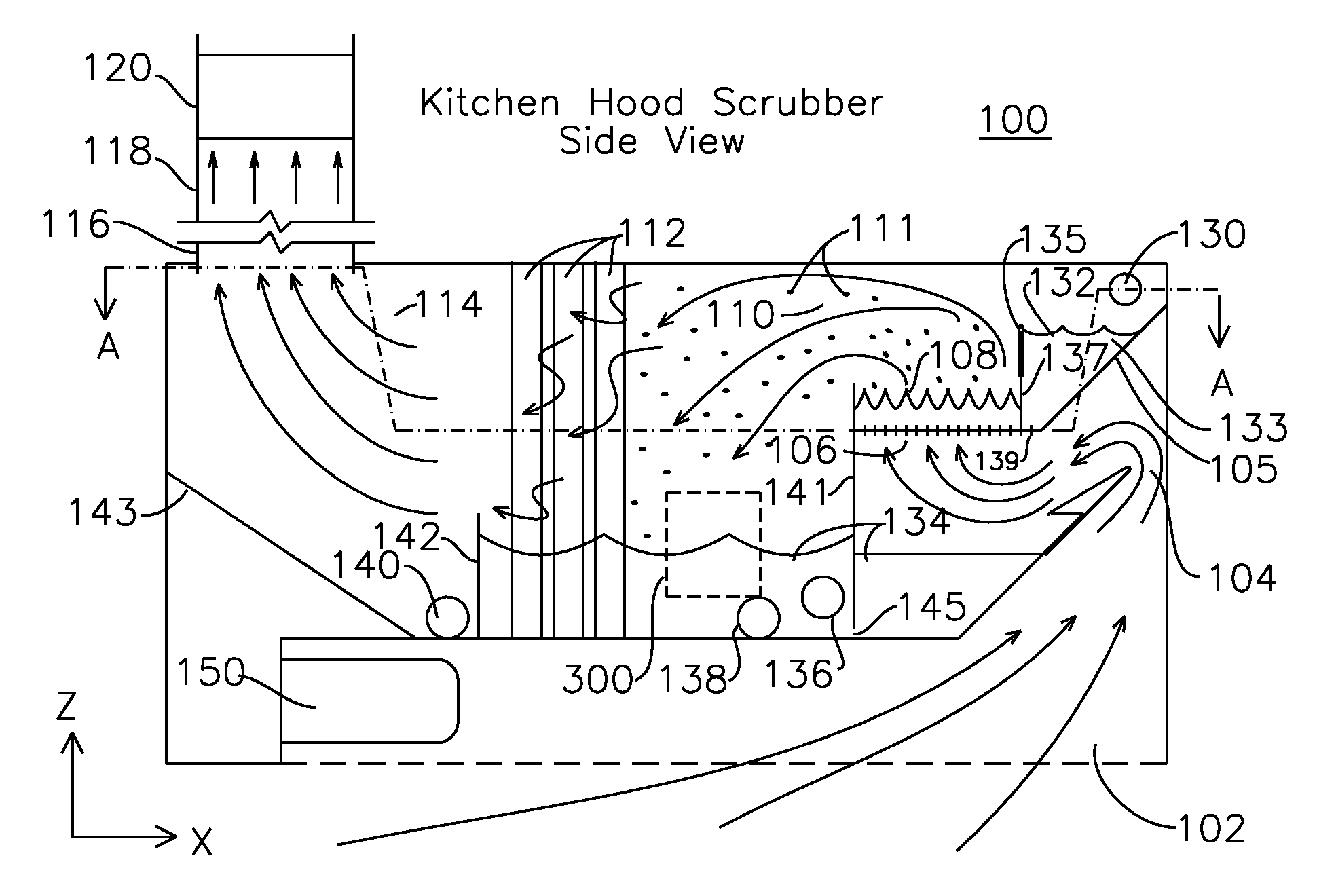
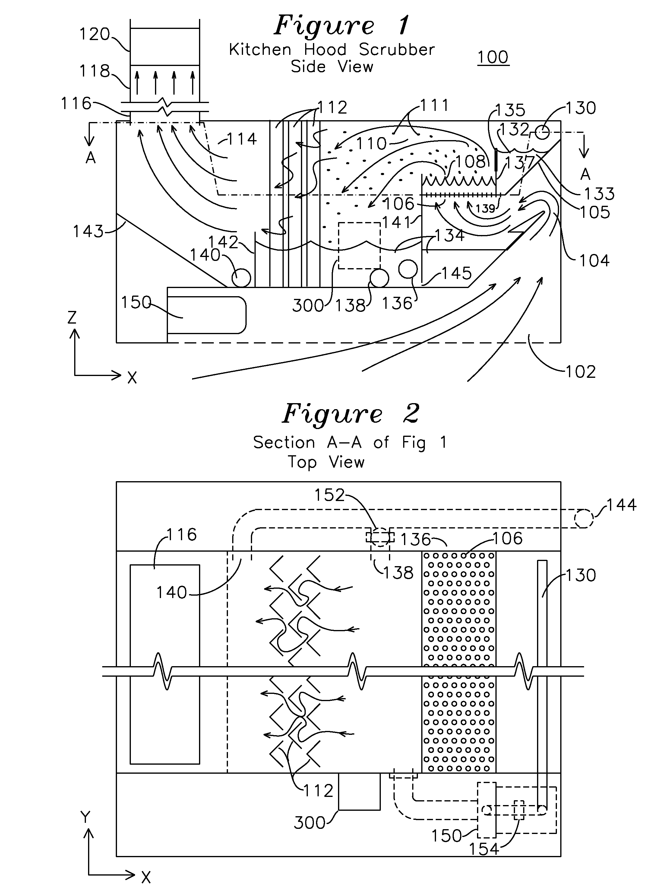
[0027]The present invention is best understood with reference to side view FIG. 1, and section A-A of FIG. 1 as shown in composite FIG. 2, which also shows other structures (as dashed lines) projected into the section for reference. The kitchen scrubber hood 100 may have the dimension of a standard kitchen exhaust hood, such as 2′ high (z axis) by 4′ wide (x axis) by any length (y axis) required. In a vent-only service mode used when the scrub mode is not available such as during service or shutdown operations or during an emergency condition such as clearing smoke from a fire, a cleaning fluid may be present in a main reservoir 134, but pump 150 is not turned on, and scrub reservoir 108 has drained back to main reservoir 134, such that incoming air enters inlet duct 102, passes through the apertures 106 of the lower surface of empty scrub reservoir 108, through the structures of the mist eliminator 112, and through the exhaust outlet. In the normal operational scrubbing mode, fan 1...


PUM

PropertyMeasurementUnit
Fractionaaaaaaaaaa
Fractionaaaaaaaaaa
Timeaaaaaaaaaa

Abstract

An air scrubber for removing oils and contaminates from air has an underside inlet for the introduction of contaminated air. The contaminated air passes through a reduced aperture passageway which prevents retrograde flow of contaminates or cleaning fluids contained in the scrubber. The contaminated air is thereafter directed upwards through a scrub reservoir having a plurality of apertures, such that the contaminated air passing through the apertures forms jets which cause interaction between the cleaning fluid and the contaminates, thereby creating droplets containing cleaning fluid with entrapped contaminates, and cleaned air. The droplets and air are directed to a mist eliminator having a plurality of chevron V structures which capture the droplets and return them to the main reservoir. A circulating pump moves cleaning fluid from the main reservoir to an upper reservoir which spills into the cleaning reservoir.

Description

RELATED APPLICATIONS[0001]The present application claims priority of U.S. Provisional Pat. No. 61 / 070,335 filed Mar. 24, 2008.FIELD OF THE INVENTION[0002]The present invention relates to an air cleaner. More particularly, the present invention relates to an air scrubber and degreaser for use above a cooking surface, the air cleaner accepting contaminated air having a mixture of cooking vapors and oils in aerosol form, separating the contaminants by placing them in solution with a cleaning fluid which is returned to a main reservoir, thereby exhausting clean air.BACKGROUND OF THE INVENTION[0003]Kitchen air cleaners are well known in the field of air handling equipment. A typical kitchen vent hood includes a grease trap such as a removable mesh for capturing airborne oils drawn through by a fan and delivered to an exhaust vent. Cooking vapors are drawn through the mesh which inefficiently captures a fraction of the airborne oils and grease, and the contained grease is extracted from t...

Claims


Application Information

Patent Timeline
IPC IPC(8): B01D47/02
CPCB01D47/021B01D2221/02
Inventor BROOKMAN, DAVID L.
Owner BROOKMAN DAVID L
Why Eureka
Try Eureka