
Offshore floating structure with motion dampers

a technology of motion dampers and floating platforms, which is applied in vessel construction, special-purpose vessels, transportation and packaging, etc., can solve the problems of not disclosing the weight of passive dampers suspended below the columns or towers, and achieves the elimination of significant bending moments, facilitates installation time and expense, and increases the natural period of platform heave

Inactive Publication Date: 2009-09-24
MANSOUR ALAA M
View PDF14 Cites 17 Cited by
  • Summary
  • Abstract
  • Description
  • Claims
  • Application Information

AI Technical Summary

Benefits of technology

[0013]Another feature and advantage of the present semi-submersible platform having passive damper weight member(s) suspended beneath the platform by flexible connection members is that it facilitates installation time and expense, by eliminating rigid structures connected between the damper weight member(s) and the hull.
[0014]Another feature and advantage of the present semi-submersible platform having passive damper weight member(s) suspended beneath the platform by flexible connection members is that it eliminates the significant bending moments that typically occur with rigid structures connected between the damper weight member(s) and the hull.
[0015]A further feature and advantage of the present semi-submersible platform having passive damper weight member(s) suspended beneath the platform by flexible connection members is that the passive damper weight is located a sufficient distance below the waterline to provide significant hydrodynamic mass and damping and in-water weight during operation which increases the platform heave natural period and improves platform stability, which provide significant reduction to the platform heave and rotational motion and consequently enables the use of the top tensioner risers.

Problems solved by technology

Moougin, U.S. Pat. No. 4,241,685 and Horton U.S. Pat. No. 6,817,309 discloses single-column or spar-type offshore floating structures having a cylindrical column or tower divided into damping chambers, but do not disclose passive damper weight members suspended below the column or tower by flexible connection members.

Method used


Image

  • Offshore floating structure with motion dampers
  • Offshore floating structure with motion dampers
  • Offshore floating structure with motion dampers

Examples


Embodiment Construction

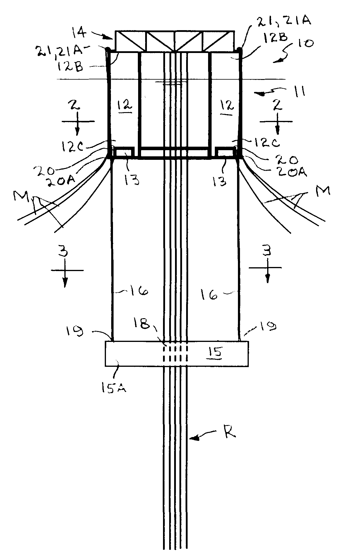
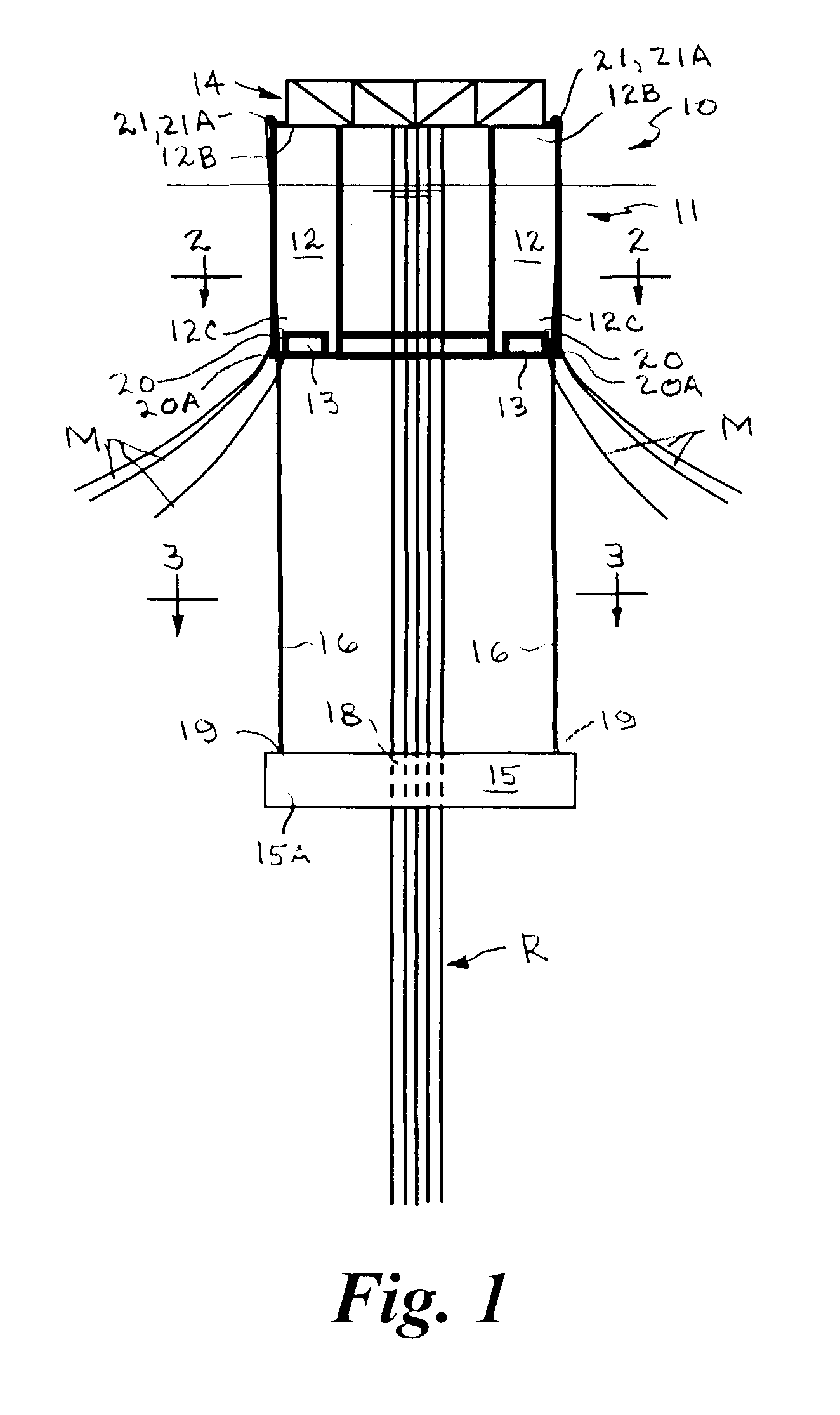
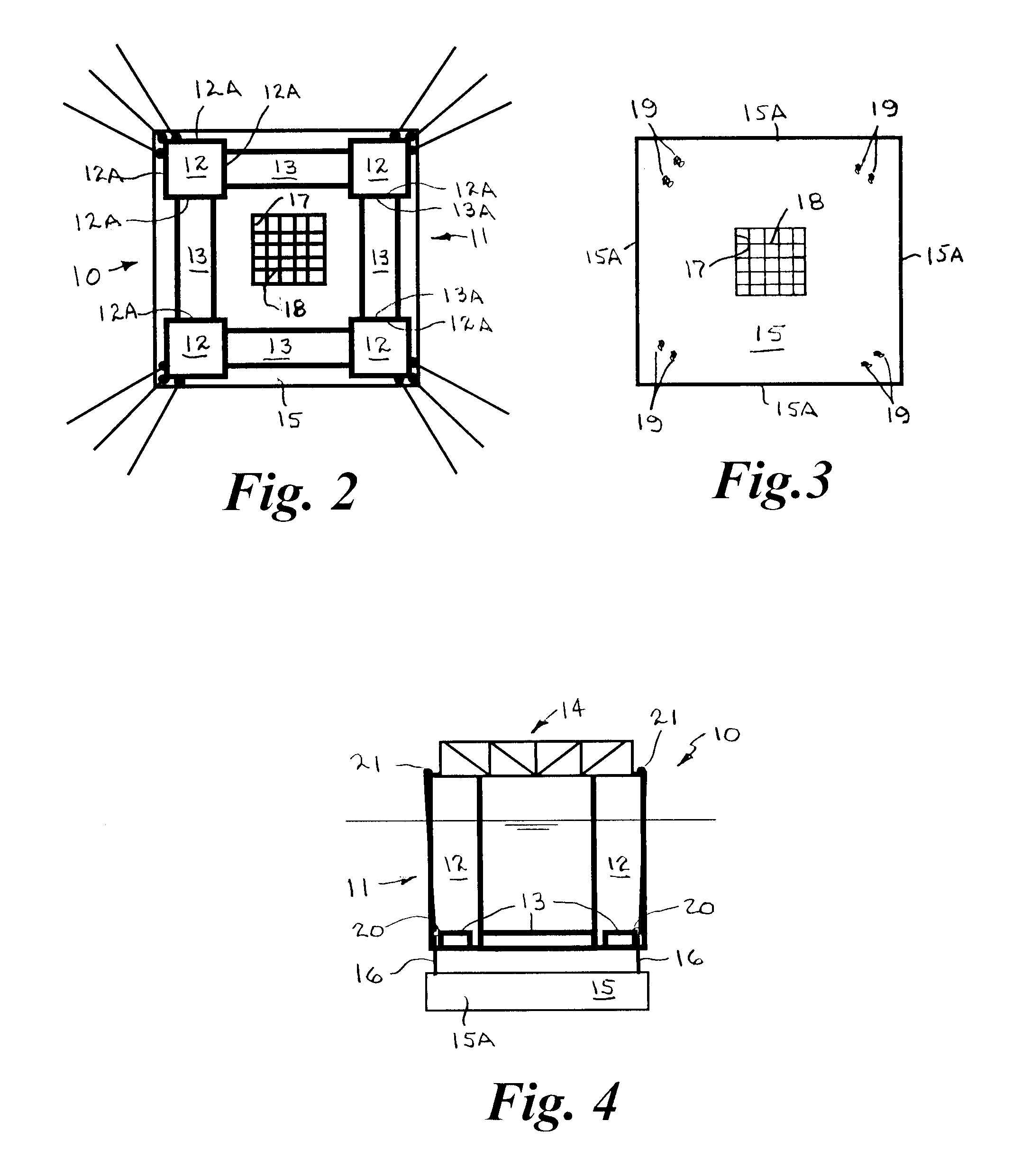
[0032]Referring to the drawings by numerals of reference, there is shown in FIGS. 1-3, a semi-submersible floating platform 10 in accordance with a first multi-column embodiment of the present invention for use in offshore applications, such as for offshore oil and gas drilling and production. The platform 10 has a hull 11 including support columns 12 having a generally a quadrilateral transverse cross section, which may be a generally rectangular or trapezoidal shaped configuration, and a generally rectangular ring-shaped pontoon structure 13 disposed between the support columns at a lower end thereof. The columns 12 and pontoons 13 are constructed substantially of flat metal plate.

[0033]Each of the support columns 12 has a generally rectangular transverse cross section formed of opposed parallel spaced sidewalls 12A, and upper and lower ends 12B and 12C. Each side of the pontoon structure 13 has a generally rectangular transverse cross section with opposed parallel spaced inboard ...


PUM


Abstract

A semi-submersible floating platform (10, 10A) for use in offshore applications has a semi-submersible hull structure (11) including support columns (12), a pontoon structure (13) adjoined to the lower ends thereof, and a deck structure (14) supported at an upper end of the columns for supporting the deck and equipment mounted thereon above the water surface. One or more passive damper weight members (15) are suspended below the hull by flexible connection members (16) at variable distances to provide hydrodynamic mass, damping, and in-water weight to the platform during operation, and the flexible connection members are maintained in tension by the damper weight(s) during operation.

Description

CROSS REFERENCE TO RELATED APPLICATION[0001]This application claims priority of U.S. Provisional Application Ser. No. 61 / 034,244, filed Mar. 6, 2008.BACKGROUND OF THE INVENTION[0002]1. Field Of The Invention[0003]This invention relates generally to offshore floating vessels and platform structures and, more particularly, to a semi-submersible floating platform having a semi-submersible hull structure, with one or more passive damper weight members suspended below the hull by flexible connection members at variable distances to provide hydrodynamic mass, damping, and in-water weight to the platform during operation.[0004]2. Background Art[0005]Haselton, U.S. Pat. No. 3,986,471 discloses apparatus for damping vertical movement of a semi-submersible vessel having a small water plan area, whose buoyancy is provided substantially completely by submerged pontoon means and which includes at least one submerged damper plate supported deep beneath the vessel by flexible tensioned support ele...

Claims


Application Information

Patent Timeline
IPC IPC(8): B63B35/44
CPCB63B21/50B63B1/107B63B2001/128B63B2039/067
Inventor MANSOUR, ALAAWYBRO, PETER G.
Owner MANSOUR ALAA M
Learn More