
Automatic feeding system for aquaculture pond

A pond and automatic technology, applied in fish farming, two-dimensional position/channel control, animal husbandry, etc., can solve the problems of ranging failure, large ranging error, affecting the propagation of sound waves, etc., and achieve accurate orientation. Improve performance, improve positioning accuracy, and prevent the effect of spinning in place

Active Publication Date: 2013-12-25
FISHERY MACHINERY & INSTR RES INST CHINESE ACADEMY OF FISHERY SCI
View PDF6 Cites 14 Cited by
  • Summary
  • Abstract
  • Description
  • Claims
  • Application Information

AI Technical Summary

Problems solved by technology

[0005] First, for the ultrasonic ranging method, since most ponds are uneven and covered with weeds, the reflection effect of the ultrasonic signal is not good, which may easily lead to the failure of ranging; in addition, because the propagation of the ultrasonic signal has a certain angle (Just like the beam of a flashlight), the farther away, the greater the coverage of the acoustic signal. When the water level of the pond is high, if the height of the pond foundation is not enough above the water surface, the signal reflection area will be small, and it can only reflect one A small part of the sound wave signal, most of the sound wave signal cannot be reflected or hit the water surface, and it is easy to cause ranging failure or ranging error; in addition, weather conditions have a great influence on ultrasonic ranging, ultrasonic waves rely on air transmission, wind (air flow ) will affect the propagation of sound waves, resulting in a large error in ranging; rain and fog will also hinder the propagation of sound waves in the air, thereby affecting the accuracy of ranging
[0006] Second, for the laser ranging method, when the soil color of the pond foundation is dark, it will absorb the laser signal energy, resulting in a shortened measurable distance or even no range measurement; in addition, the weeds growing on the pond foundation will also affect the laser signal reflection
[0007] Third, the left and right shaking of the hull will cause the emission direction of the ultrasonic beam or laser beam to shake up and down, causing the signal to hit the water surface or cross the ridge, resulting in ranging errors or ranging failures
[0008] Fourth, the device judges whether the course of the hull is parallel to the foundation of the pond by comparing the signal propagation time of the two probes installed on the corner of the bow and the side of the hull. The premise is that the surface of the foundation of the pond must be straight. If the pond ridge There are weeds or bumps, which lead to a large error in distance measurement, and there will be a large error in orientation; in addition, even if the surface of the pond foundation is flat, when the hull is subject to sudden wind or current rotation, such as turning 90 degrees from the original direction At this time, the detector measures not the distance from the original pond base, but the distance from the other side of the pond base that intersects with the original pond base, so that the hull will lose the correct course
The hull forward controller is installed on one side of the hull, so the hull is actually subjected to an asymmetric forward pushing force located on one side of the hull during the forward movement, so when the hull is moving forward, the forward controller The steering controller and the steering controller must constantly work alternately to ensure the course. The frequent switching control of the two controllers will affect the stability of the hull, and even cause the feeding hull to "spin in place".
[0010] In addition to the defects in the above route control method, the device adopts a single-hull structure. When the hull swings from side to side, this structure will also affect the stability of the hull manipulation (such as steering). If the center of gravity of the hull is relatively high at this time , in severe cases, it may even cause the hull to roll over

Method used


Image

  • Automatic feeding system for aquaculture pond
  • Automatic feeding system for aquaculture pond
  • Automatic feeding system for aquaculture pond

Examples


Embodiment Construction

[0049] The present invention will be further described below in conjunction with accompanying drawing.

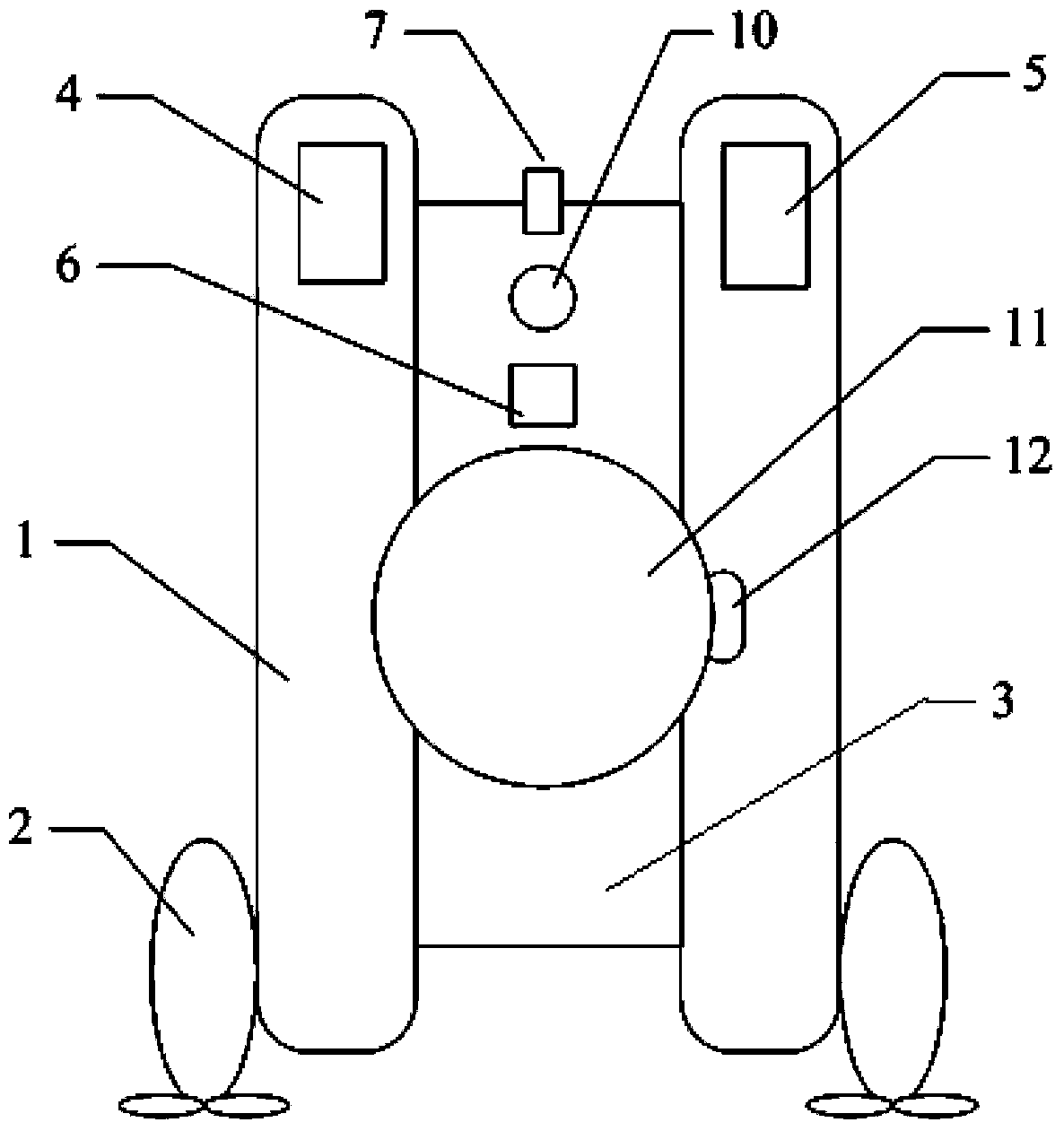
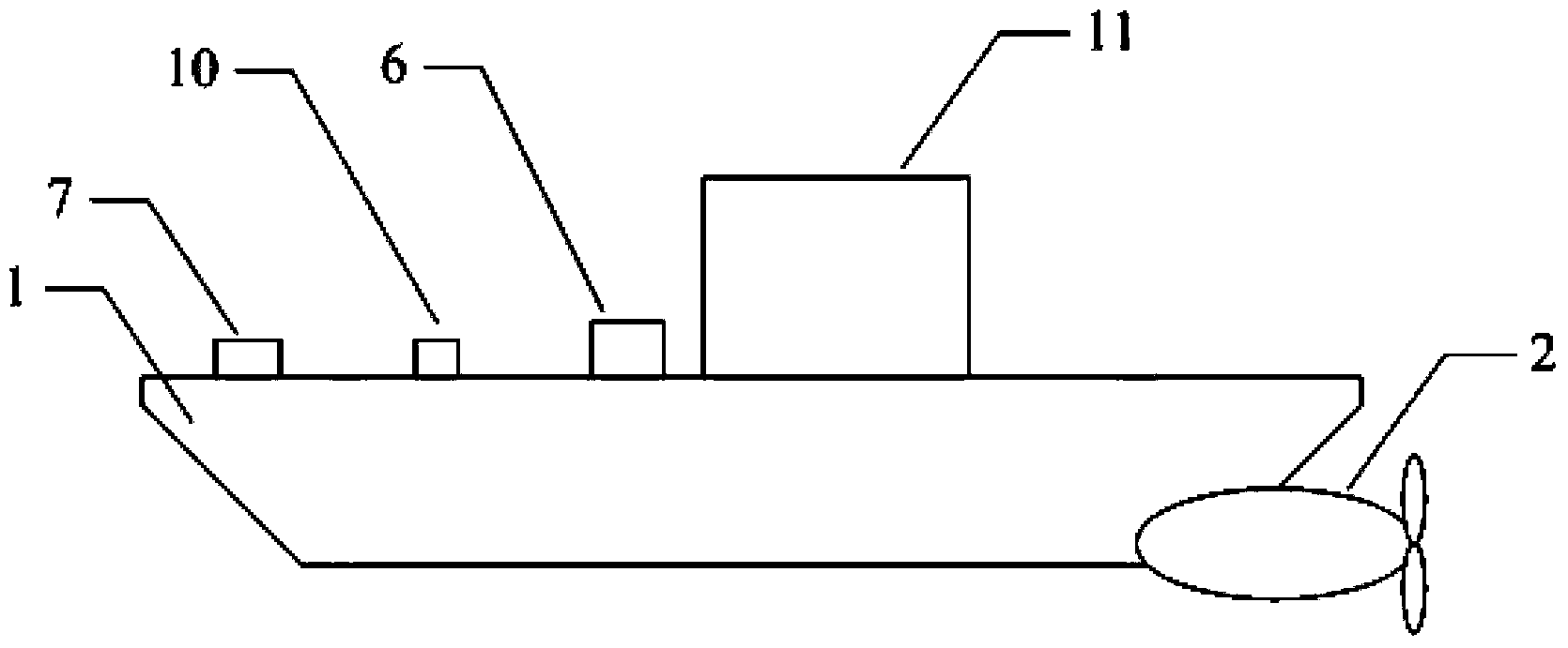
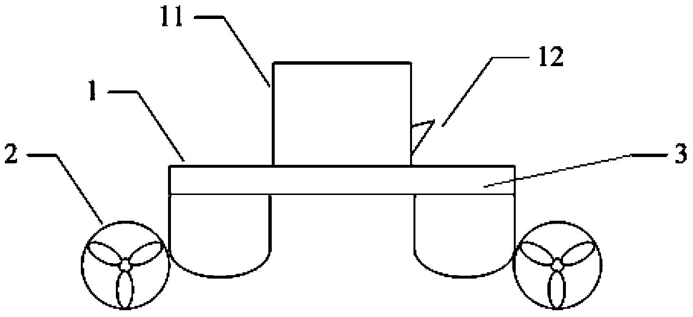
[0050] Figure 1~3 It is a structural diagram of the feeding hull and its load. The feeding hull 1 is a double-hull structure, consisting of two parallel boat-shaped floating bodies floating on the water surface and a deck 3 that covers the two boat-shaped floating bodies and connects the two as a whole; Electronic compass 10, wireless signal receiver 7, controller 6 and feeding machine 11 are installed on the deck 3;

[0051] The control and execution unit of the present invention mainly includes a controller 6 , a wireless signal transmitter, a wireless signal receiver 7 , an electronic compass 10 and a propeller 2 . Two wireless signal transmitters are installed on the base of the pond at intervals, and the electronic compass 10 monitors the instant heading of the feeding hull 1, and feeds back to the controller 6, and the wireless signal receiver 7 receives the wireles...


PUM


Abstract

Disclosed is an automatic feeding system for an aquaculture pond. The aquaculture pond is rectangular, the system comprises a feeding hull, a controller and a feeder, the feeding hull is of a twin-hull structure and comprises two parallel boat-shaped buoys and a deck, the two parallel boat-shaped buoys float on the water and are covered and connected into a whole by the deck, an electronic compass, a wireless signal receiver, the controller and the feeder are mounted on the deck, two wireless signal transmitters are mounted on a buttress of the pond at intervals, two screw propellers are symmetrically mounted on the left side and the right side of a stern of the feeding hull, one screw propeller is arranged on each boat-shaped buoy, the electronic compass monitors the instant course of the feeding hull and feeds the instant course back to the controller, the wireless signal receiver receives wireless signals transmitted by the wireless signal transmitters and feeds the wireless signals back to the controller, and the controller controls running of the two screw propellers. Positioning and orienting of the feeding hull in the patrolling process are not affected by the buttress of the pond and weather factors, and sailing and steering stability is better.

Description

technical field [0001] The invention relates to the field of prawn cultivation in ponds, in particular to an automatic feeding technology for breeding feed. Background technique [0002] Shrimp is an important aquaculture species in my country. Feed feeding is an important daily work during shrimp farming. Due to the special living habits of prawns, it is necessary to distribute the feed evenly around the pond. At present, feeding in shrimp ponds is mainly done manually, which is labor-intensive and difficult to achieve uniform feeding. [0003] The patent application number 201120380114.5 "A device for feeding shrimp that can automatically patrol the pond" discloses a boat that can automatically patrol the pond for feeding shrimp. The device adopts a single hull structure, and the route of the hull in the pond is as follows: Controlled: Use three probes installed on the front of the bow, the corner of the bow and the side of the hull to detect the distance between the fr...

Claims


Application Information

Patent Timeline
IPC IPC(8): A01K61/02G05D1/02
Inventor 唐荣汤涛林邹海生杨家朋苗雷刘世晶陈军刘兴国
Owner FISHERY MACHINERY & INSTR RES INST CHINESE ACADEMY OF FISHERY SCI
Learn More