
Retinal rest device and method

a chin support and chin support technology, applied in the field of external supports, can solve the problems of neck pain, neck strain, uncertain end use applications, etc., and achieve the effect of not overly complicated in design and/or mechanics, and low manufacturing cos

Inactive Publication Date: 2009-09-24
ALSTOM TRANSPORT SA
View PDF5 Cites 3 Cited by
  • Summary
  • Abstract
  • Description
  • Claims
  • Application Information

AI Technical Summary

Benefits of technology

"The invention is a device that can be used on patients who have had surgery or therapy on their head and need to keep their head tilted downward for a long time. It can be worn without a sling or neck brace and provides comfort while keeping the head tilted enough. It can also be used during eye surgery to help with airway maintenance. The device is easy to use and dispose of after use."

Problems solved by technology

Maintaining the prescribed face-downward position is difficult for the typical patient at best and can lead to fatigue, soreness and strain on the neck, shoulder and back muscles that are called upon to actively maintain this therapeutic positioning.
But it is not especially clear how that design works and / or where it would be positioned for a recovering patient.
Other pillow designs have been conceived and patented but for uncertain end use applications.
Furthermore, its chin support did not appear to provide any neck / mandible support regardless of the degree of inflation imparted.

Method used


Image

  • Retinal rest device and method
  • Retinal rest device and method
  • Retinal rest device and method

Examples


first embodiment

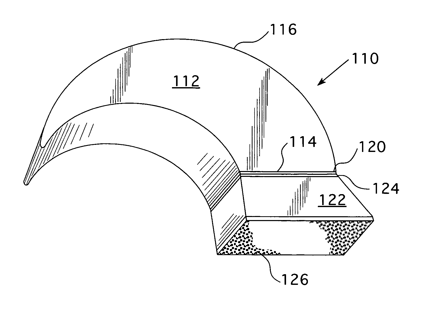
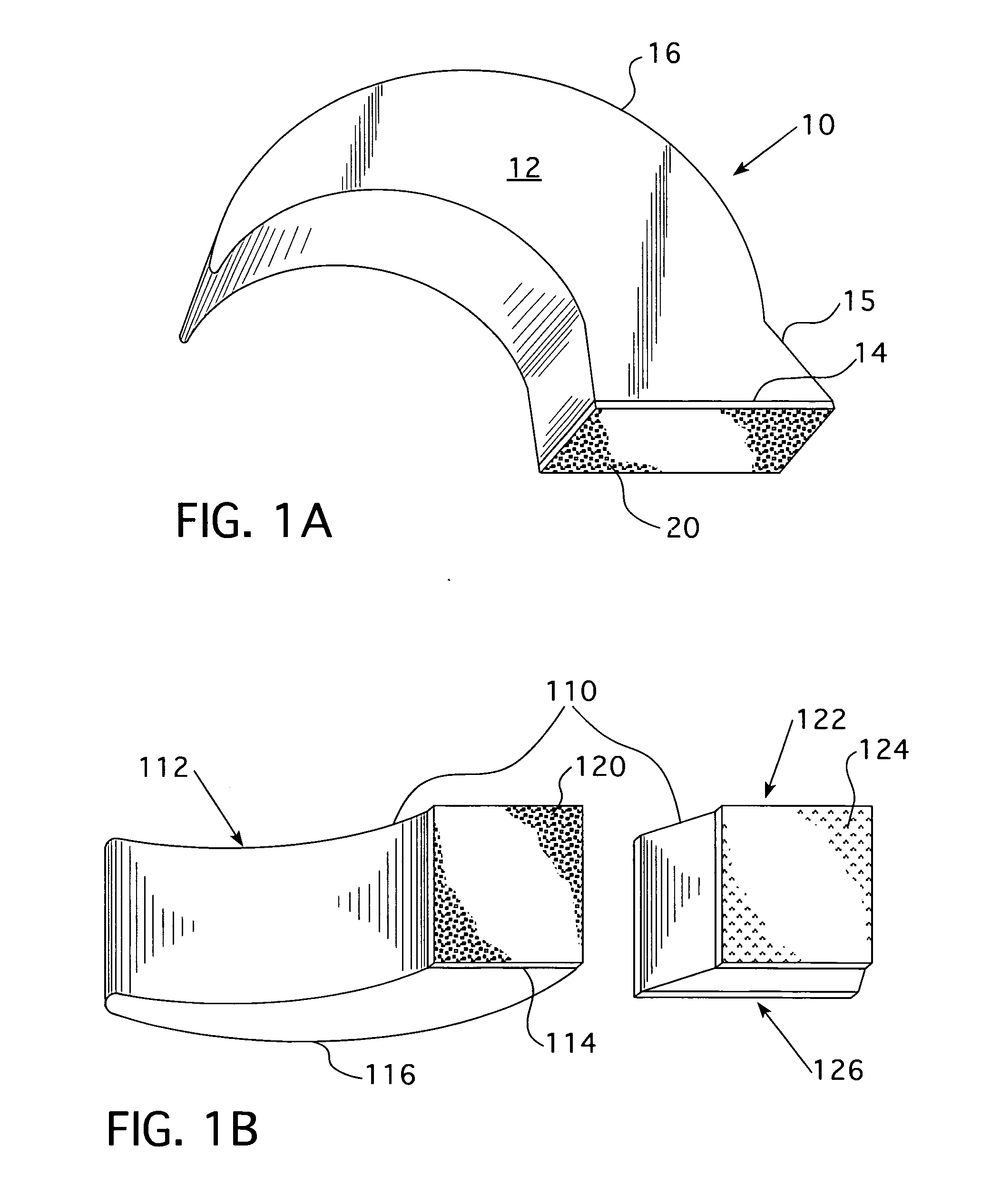
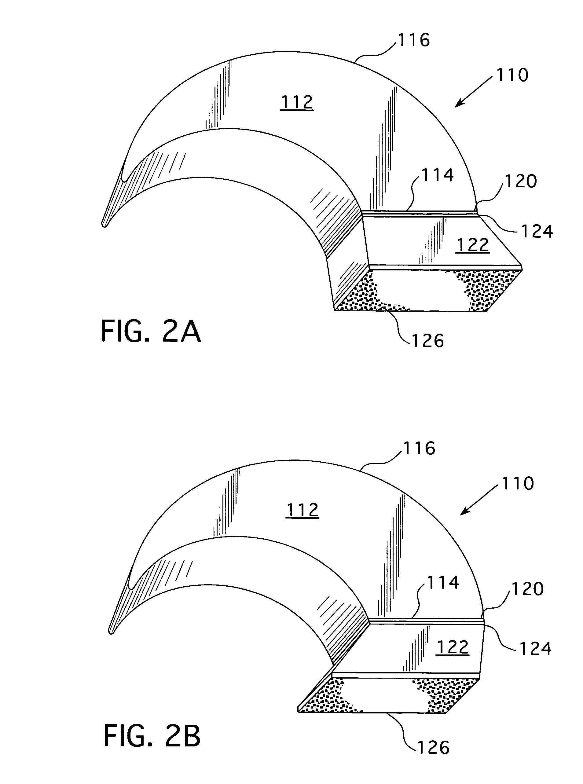
[0039]Referring to accompanying FIG. 1A, there is shown a first embodiment for a disposable retinal rest support, generally 10. That one piece unit has as its main component, a crescent-shaped manubrium arch 12, together with means for positioning said crescent arch 12 for repeated installation between the user / wearer's chin and manubrium or chest. The flat base 14 to crescent arch 12 is kept substantially planar for better resting, and adhesion, directly to the user / wearer's manubrium. Preferably, flat base 14 has an inclined front face portion 15 for providing some structural support to the crescent arch when secured directly to the user / wearer's chest (rather than mounting to a wedge-shaped spacer that mounts to the wearer's chest).

[0040]As shown, crescent arch 12 has a curved upper (or outer) surface 16. Alternatively, upper surface 16 of crescent arch 12 may consist of several consecutive planar portions giving the rest support more of a polygonal appearance in side view (not s...

second embodiment

[0043]In FIGS. 5 through 7, there is shown alternate means for mounting support 210 to its wearer / user, that alternative means employing greater direct adhesion, at more than one contact point, to the wearer's chest and neck regions. At one end of upper surface 216 (whether curved or polygonal) to support 210, there is positioned a second adhesive-attachment section 230. Both first section 220 and second section 230 have corresponding sections of Velcro® components. As best seen in FIGS. 6 and 7, there is a somewhat square, or rectangular shaped, section of Velcro® for adhering to the user / wearer's chest, a so-called chest patch 232. A more rounded top and bottom section of hook Velcro® can be adhered, more comfortably due to its top and bottom curvatures, to the same user / wearer's chin C. Hereafter, that component is referred to as chin patch 234.

[0044]For applying chest patch 232 and chin patch 234 to the respective manubrium M and chin C regions of a user / wearer, several surgical...


PUM


Abstract

A hands free, support device for use on a patient convalescing from ophthalmologic surgery such as the type used to reattach a detached retina. The device can be repeatedly positioned between the base of a user / wearer's chin / jaw and upper chest so that no wrap around neck or head sling attachment means are required. When installed, the device will keep the user / wearer's chin tilted downward and toward the upper chest. A related method is also disclosed.

Description

CROSS-REFERENCE TO RELATED APPLICATION [0001]This application claims priority to U.S. Provisional application Ser. No. 61 / 070,349, filed on Mar. 22, 2008, the disclosure of which is fully incorporated by reference herein.FIELD OF THE INVENTION [0002]This invention relates to external supports for assisting patients recuperating from certain surgical procedures. Particularly, the invention relates to a device, and related method, for individuals who desire to be ambulatory, but must still keep their heads downwardly tilted for a prolonged recovery period. More particularly, this invention relates to a chin support / rest for individuals recovering from retinal reattachment and other similar eye surgeries. The invention is especially suited for such individuals to keep their heads properly angled or tilted while not in a horizontal, planar (i.e. “face down”) position.BACKGROUND OF THE INVENTION [0003]In a representative surgical procedure for repairing an individual's detached retina, a...

Claims


Application Information

Patent Timeline
Patent Type & Authority Applications(United States)
IPC IPC(8): A47G9/10
CPCA61F9/00727A47C16/00
Inventor DERRICK, JOYCE A.DERRICK, STEVE J.
Owner ALSTOM TRANSPORT SA
Learn More