
High-Pressure Apparatus and Method for Removing Scale from a Tank

a technology of scale removal and high-pressure apparatus, which is applied in the direction of cleaning process and apparatus, chemistry apparatus and processes, and using liquids to clean, etc., can solve the problems of difficult cleaning problems, no one cleaning system will work adequately for all tanks, and it is difficult to find a single cleaning tool that fits all tanks and applications

Active Publication Date: 2009-09-24
ACCONDA LLC
View PDF21 Cites 11 Cited by
  • Summary
  • Abstract
  • Description
  • Claims
  • Application Information

AI Technical Summary

Benefits of technology

[0014]This invention synchronizes the transversal and rotational movements of water jets. While the jets are directed at a pre-adjusted distance to the vessel wall, they are moved in three dimensions. This movement results in a controlled spiral or helical cleaning track along the vessel walls. The travel speed of the water jets and the distance between adjacent cleaning tracks can be adjusted to match the cleaning needs so that there is a predetermined overlap from one cleaning track to the next. In this way, the entire inner surface of the vessel can be covered precisely. Once the cleaning tool has been moved from one end of the vessel to the other with the travel of the water jets controlled in that manner the vessel wall will have been thoroughly cleaned. The exact positioning of the water jets allows the removal of very hard deposits.
[0016]Thus, the present invention provides a vessel cleaning system for cleaning storage tanks, reactors, etc. in all industries. The system of this invention is directed to cleaning many different types of deposits, especially very hard deposits from vessel walls using high pressure water jets. A spray sub-system comprises a tool carrier with water jet nozzles attached thereto which unfolds by rotating and telescoping inside the vessel at the start of a cleaning cycle and folds up at the end of the cleaning cycle. The unfolding and folding procedure is required to get the tool carrier in and out of the tank through a relatively small access so that the cleaning system is still able to position water jets at a required distance to a vessel wall and therefore deposits to be removed from the vessel wall. The unfolding and folding procedure is speed controlled and simultaneously used to clean certain areas inside the vessel.

Problems solved by technology

Since the tanks are custom designed and thus may have different interior geometries, no one cleaning system will work adequately for all tanks.
Also, many processes in these types of plants or factories leave a hard, tenacious scale on interior surfaces of tanks, which presents an especially difficult cleaning problem.
That restriction presents the engineering dilemma of having to insert the tool through a small opening (so the tool has to be small), but requiring a substantial distance for a water jet from the tool, in order to reach the farthest surfaces of the interior of the tank.
With all of these factors in mind, one can see that it is difficult to find a single cleaning tool that fits all tank sizes and applications while doing a good job of cleaning the interiors of all of the tanks.
For this type of water jet cleaning system, surface coverage cannot be exactly controlled since the water jet tracks contact the interior surface of the tank at more or less random locations.
If there is too great an overlap, then the track will be directed too much to a portion of the interior surface which has already been cleaned and the process is therefore inefficient.
Such systems are also inefficient since the majority of time the spray from the jets is not effective directed to the wall of the vessel, but either up or down away from the surface to be cleaned.
Furthermore, since the distance from the center axis of the tank, where the jets are typically located, to the interior surface of the tank may be several feet, hard deposits cannot be adequately removed and thus the cleaning process is more a flushing process.
Systems for cleaning the interior surfaces of a tank encounter another serious problem in that the inside of the tank typically includes structural support plates extending laterally inwardly toward the axis of the tank.
These plates represent surfaces which must be cleaned, and also present obstacles for the movement of the cleaning tool within the tank or vessel.
Unfortunately, such systems are highly complex, require a long setup time, and are very heavy and expensive.
Further, the time and expense required to program and debug the programmable controller is often longer and greater than the total cost of a satisfactory cleaning job without such a controller.
Since the system must be re-programmed for each tank geometry, such systems are currently not cost effective.

Method used


Image

  • High-Pressure Apparatus and Method for Removing Scale from a Tank
  • High-Pressure Apparatus and Method for Removing Scale from a Tank
  • High-Pressure Apparatus and Method for Removing Scale from a Tank

Examples


Embodiment Construction

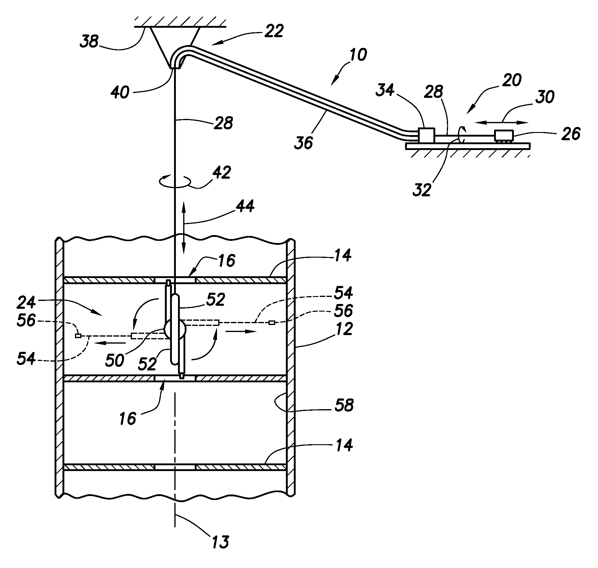
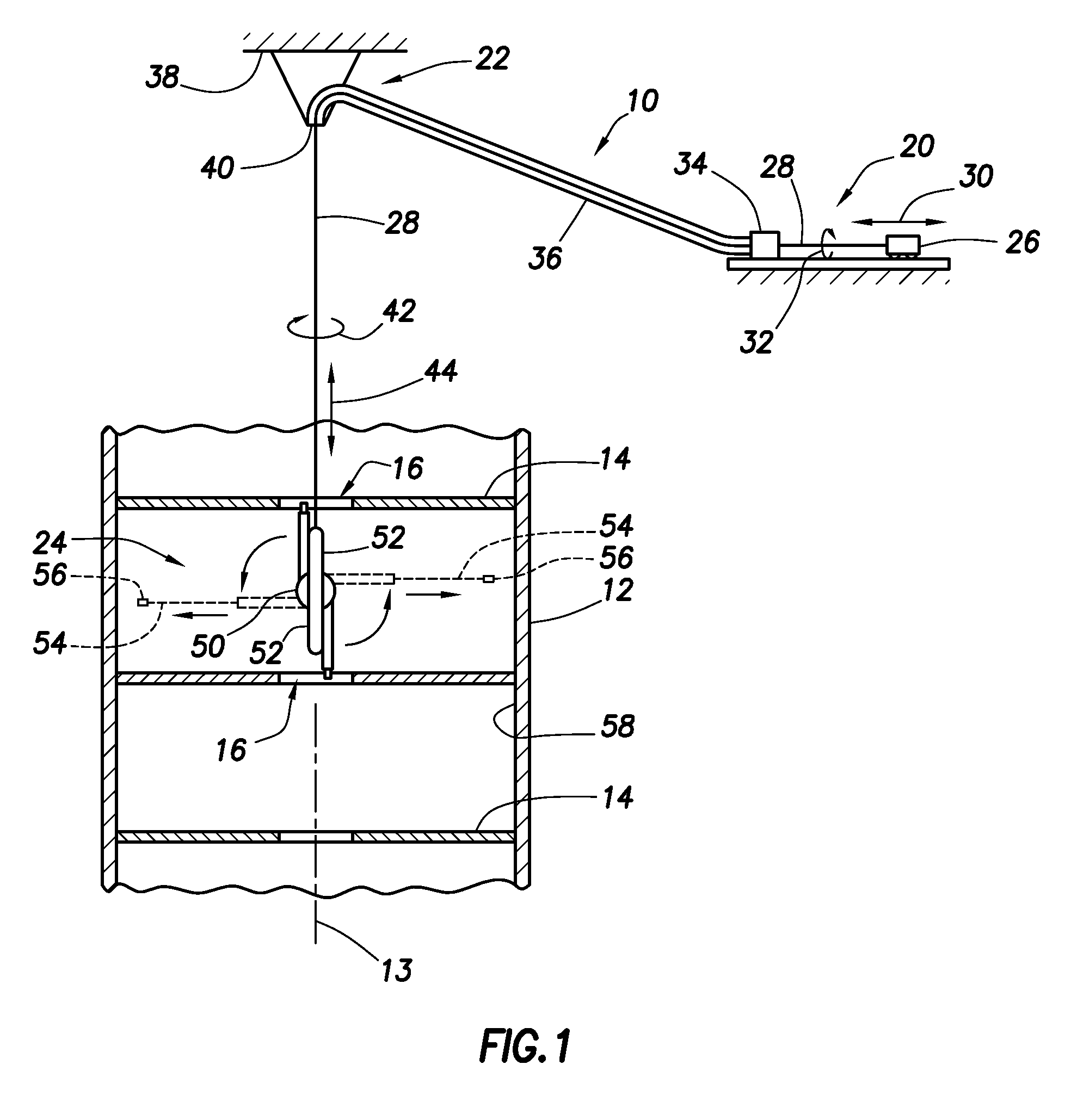
[0026]FIG. 1 illustrates a presently preferred embodiment of the tank cleaning system 10 of this invention in a tank 12 with dividing plates 14 and a center hole 16 in each dividing plate. The tank is circular in cross section and oriented vertically along an axis 13. It should be understood that only a portion of the tank 12 is illustrated, and it may extend a substantial distance above and / or below the portion illustrated in FIG. 1.

[0027]The system 10 comprises a feed sub-system 20, a support 22, and a nozzle jet sub-system 24. The feed sub-system 20 includes a prime mover 26 which imparts lateral movement to a feed tube 28 as shown by an arrow 30. The prime mover 26 also imparts rotational movement to the feed tube 28, as shown by an arrow 32. The feed tube carries fluid, typically water, under high pressure for cleaning the interior of the tank 12 as described in greater detail below. The high pressure fluid is provided by a high pressure source, typically a compressor (not show...


PUM


Abstract

A rotating and telescoping cleaning system improves high pressure water cleaning of the inner surfaces of vessels or tanks. Vessels can be vertically divided with dividing plates with centered through-holes. Synchronized and controlled transverse and rotary movements of water jets result in a controlled spiral or helical cleaning track along the vessel walls. The water jets are directed at a pre-adjusted distance from the vessel wall and the travel speed of the water nozzle jets is exactly controlled allowing the removal of very hard deposits. One pass with the tool carrier with operating water jets along the length axis of the vessel results in a thoroughly cleaned vessel wall. The tool unfolds and folds inside of the vessel powered by the flow of the high pressure cleaning water.

Description

[0001]This is a Continuation-in-Part of U.S. patent application Ser. No. 11 / 163,223, filed Oct. 11, 2005, which application claims priority from Provisional U.S. patent application Ser. No. 60 / 618,488 filed Oct. 13, 2004.FIELD OF THE INVENTION[0002]The present invention relates generally to the field of systems for cleaning the interiors of tanks by removing scale build-up using a fluid at high pressure and, more particularly, to a system and method for altering the axis of rotation and diameter of spray nozzles in such a cleaning system to maximize the efficiency of the cleaning process.BACKGROUND OF THE INVENTION[0003]Most tanks in chemical plants, refineries, and similar factories are custom designed vessels that have to be cleaned periodically. Since the tanks are custom designed and thus may have different interior geometries, no one cleaning system will work adequately for all tanks. Furthermore, vessels are typically divided with dividing plates which include centered through...

Claims


Application Information

Patent Timeline
IPC IPC(8): B08B9/093
CPCB05B3/06B08B9/0936B08B9/093
Inventor GEPPERT, CHRISTIANSCHROTH, STEFAN
Owner ACCONDA LLC
Learn More