Heat exchange device

a heat exchange device and heat exchange technology, applied in the direction of heat exchange apparatus, thermoelectric device with peltier/seeback effect, light and heating apparatus, etc., can solve the problems of degrading the reliability of the thermoelectric module b>50/b>i, difficult to sufficiently release the thermal stress of the thermoelectric, and reducing the maximum heat absorption coefficient (qmax), so as to reduce the thermal resistance and improve the reliability against thermal stress. , the effect of increasing th

Inactive Publication Date: 2009-09-24
YAMAHA CORP
View PDF9 Cites 22 Cited by
  • Summary
  • Abstract
  • Description
  • Claims
  • Application Information

AI Technical Summary

Benefits of technology

[0012]It is an object of the present invention to provide a heat exchange device which is improved in heat absorption by reducing thermal resistance and which achieves high reliability by reducing thermal stress.
[0014]Since one of the heat-dissipation electrode and heat-absorption electrode is not equipped with a substrate and is thus reduced in thermal resistance, it is possible to increase the maximum heat absorption coefficient (Qmax). The thermoelectric elements are bonded via the insulating resin layer so as to support one of the heat-dissipation electrode and heat-absorption electrode, thus eliminating the necessity of a substrate.
[0015]Thermal stress occurring in the corrugated fins is absorbed by the non-joint regions aligned in the gaps between adjacent joint regions, thus improving reliability against thermal stress. By completely eliminating the necessity of a substrate with respect to both of the heat-dissipation electrode and heat-absorption electrode, it is possible to further reduce thermal resistance, thus further increasing the maximum heat absorption coefficient (Qmax).
[0016]Since the width of the joint region is larger than the width of the gap formed between adjacent joint regions, it is possible to efficiently transmit heat generated by the thermoelectric elements to the corrugated fins, thus improving heat exchange efficiency. It is preferable that the insulating resin layer be composed of a polyimide resin or epoxy resin which is doped with fillers having high thermal conductivity such as alumina powder, aluminum nitride powder, and magnesium oxide powder.

Problems solved by technology

This makes it difficult to sufficiently release thermal stress from the thermoelectric elements 58, thus degrading the reliability of the thermoelectric module 50a against thermal stress.

Method used


Image

  • Heat exchange device
  • Heat exchange device
  • Heat exchange device

Examples


first embodiment

1. FIRST EMBODIMENT

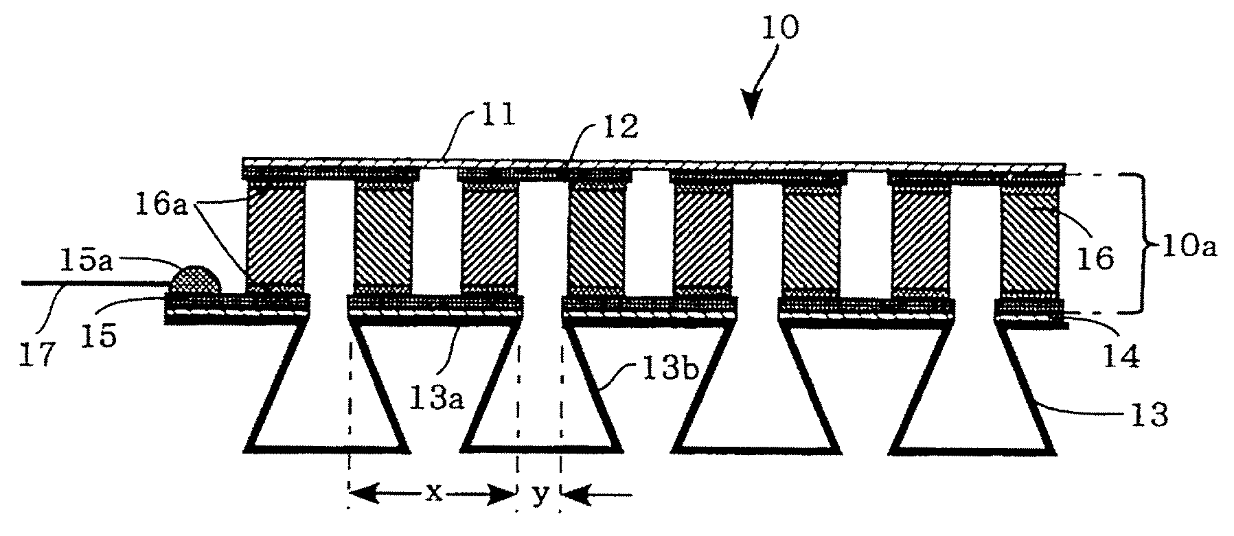
[0028]FIG. 1 is a cross-sectional view showing the constitution of a heat exchange device 10 according to a first embodiment of the present invention. The heat exchange device 10 is constituted of a substrate 11, a heat-dissipation electrode 12 which is formed below the substrate 11, a plurality of corrugated fins 13 (collectively serving as a heat exchanger on a heat-absorption side, a heat-absorption electrode 15 which is bonded onto the upper surfaces of the corrugated fins 13 via an insulating resin layer 14 having a high heat conductivity and an adhesive property, and a plurality of thermoelectric elements 16 which are electrically connected in series between the electrodes 12 and 15 via a soldering layer (or a metal) 16a.

[0029]A pair of terminals 15a is formed on one end of the heat-absorption electrode 15 in order to establish electric connections with leads 17. A thermoelectric module 10a is constituted of the heat-dissipation electrode 12, the heat-absor...

second embodiment

2. SECOND EMBODIMENT

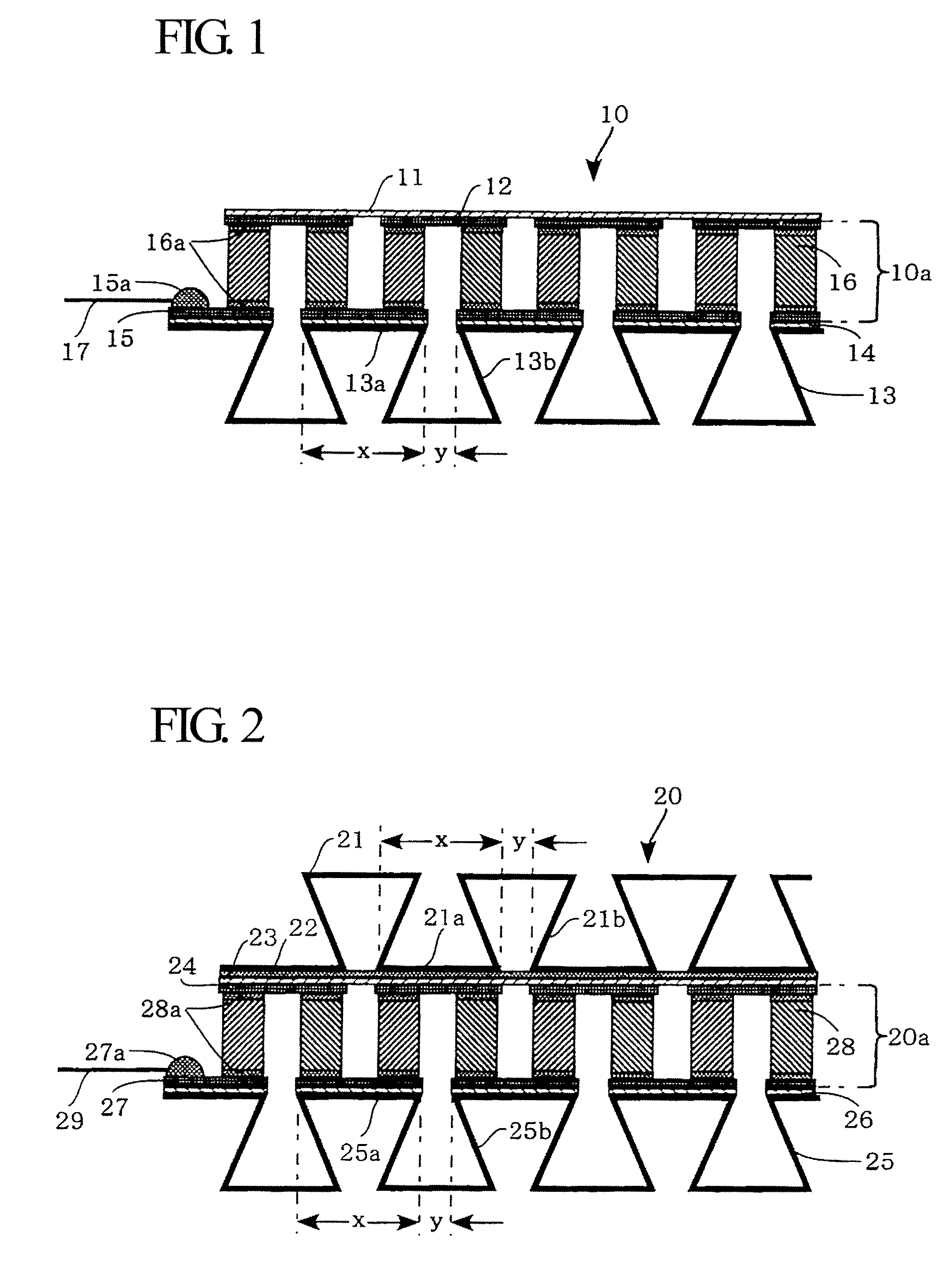
[0041]FIG. 2 is a cross-sectional view showing the constitution of a heat exchange device 20 according to a second embodiment of the present invention.

[0042]In contrast to the heat exchange device 10 where the corrugated fins 13 are arranged on the heat-absorption electrode 15 only, the heat exchange device 20 is designed such that corrugated fins are arranged on both of the heat-absorption and heat-dissipation sides. The heat exchange device 20 has a thermoelectric module 20a which is similar to the thermoelectric module 10a installed in the heat exchange device 10.

[0043]Specifically, the heat exchange device 20 includes first corrugated fins 21 (which collectively serve as a heat-dissipation side heat exchanger), a joint film 22 composed of a copper film or copper alloy film for entirely covering the lower surfaces of the first corrugated fins 21, and a heat-dissipation electrode 24 which is attached to the joint film 22 via an insulating resin layer 23 having ...

third embodiment

3. THIRD EMBODIMENT

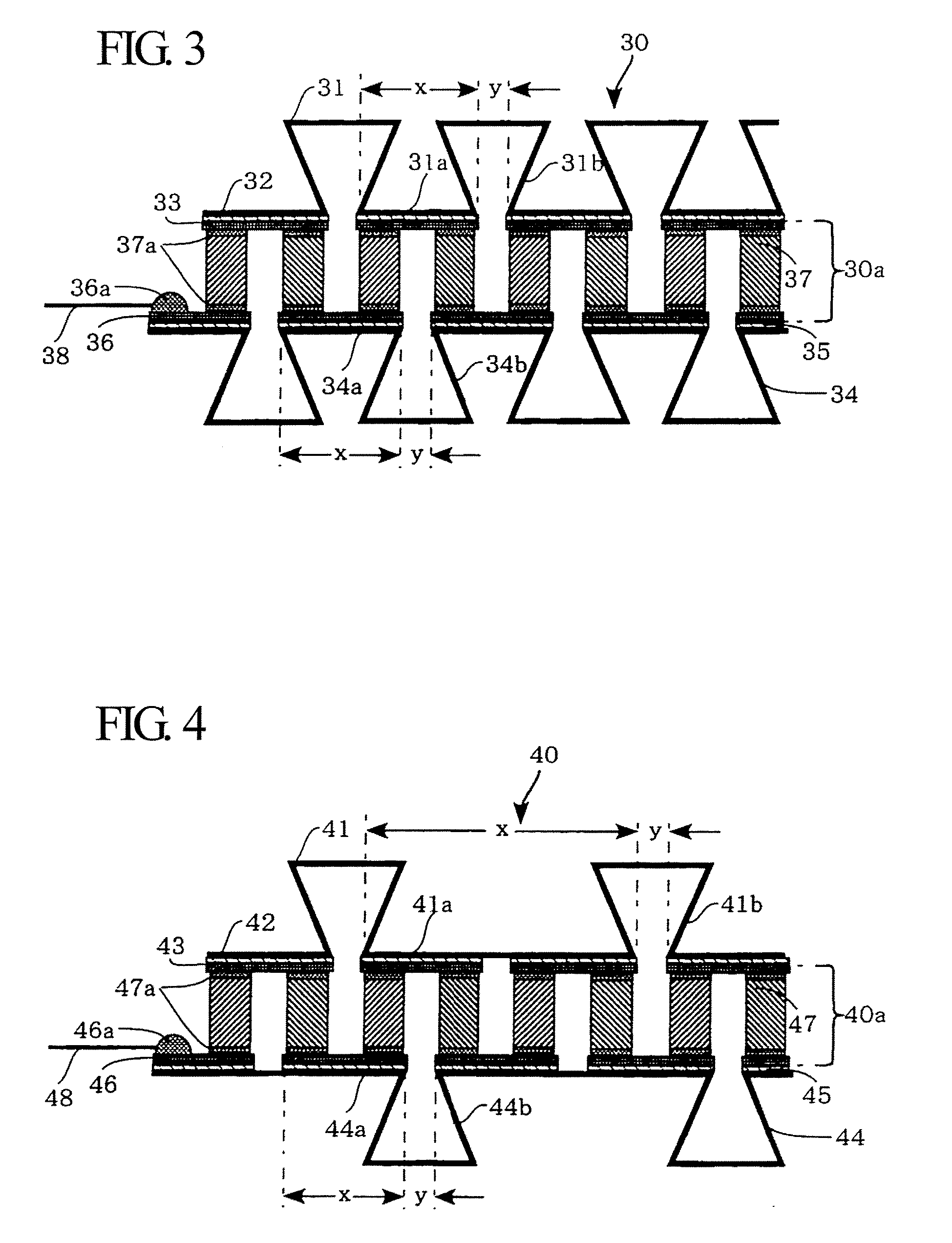
[0052]FIG. 3 is a cross-sectional view showing the constitution of a heat exchange device 30 according to a third embodiment of the present invention.

[0053]In the heat exchange device 20, the lower surfaces of the corrugated fins 21 are entirely covered with the joint film 22, the lower surface of which is entirely covered with the insulating resin layer 23; but this is not a restriction. It is possible to dispose an insulating resin layer in connection with only the joint regions of corrugated fins without intervention of a joint film. The heat exchange device 30 is designed to dispose an insulating resin layer in connection with only the joint regions of corrugated fins without using a joint film. As shown in FIG. 3, the heat exchange device 30 has a thermoelectric module 30a similar to the thermoelectric module 10a installed in the heat exchange device 10.

[0054]Specifically, the heat exchange device 30 includes first corrugated fins 31 (which collectively serve...


PUM


Abstract

A heat exchange device includes a heat exchanger disposed in connection with at least one of a heat-dissipation electrode and a heat-absorption electrode, between which a plurality of thermoelectric elements is connected in series, via an insulating resin layer, which is composed of an epoxy resin or polyimide resin doped with fillers having high thermal conductivity, without intervention of a substrate. The heat exchanger corresponds to a plurality of corrugated fins which are constituted of a plurality of joint regions joining with one of the heat-dissipation electrode and heat-absorption electrode and a plurality of non-joint regions projecting externally from a plurality of gaps formed between the joint regions adjacently aligned together, wherein the joint regions and non-joint regions are alternately aligned. Thus, it is possible to achieve high reliability by reducing thermal resistance and thermal stress while increasing the maximum heat absorption coefficient (Qmax).

Description

BACKGROUND OF THE INVENTION[0001]1. Field of the Invention[0002]The present invention relates to heat exchange devices including heat exchangers coupled with thermoelectric modules having thermoelectric elements connected in series between heat-dissipation electrodes and heat-absorption electrodes.[0003]The present application claims priority on Japanese Patent Application No. 2008-71723, the content of which is incorporated herein by reference.[0004]2. Description of the Related Art[0005]Conventionally-known thermoelectric modules are designed such that different types of thermoelectric elements composed of P-type and N-type semiconductors are alternately aligned and connected in series between heat-dissipation electrodes and heat-absorption electrodes via bonding metals such as solders. Various techniques have been developed to improve heat dissipation efficiency in thermoelectric modules, wherein heat exchangers are coupled to heat-dissipation substrates or heat-absorption substr...

Claims


Application Information

Patent Timeline
Patent Type & Authority Applications(United States)
IPC IPC(8): F28F7/00
CPCH01L35/30H10N10/13
Inventor HORIO, YUMA
Owner YAMAHA CORP
Why Eureka
Try Eureka