Dual frequency hub mounted vibration suppressor system

a technology of vibration suppressor and hub, which is applied in the direction of computer control, temperatue control, liquid fuel engine components, etc., can solve the problems of premature failure of system components, increased profile dimension, and increased profile drag of isolator, so as to reduce the in-plane vibration of the rotating system, reduce the np vibration of the main rotor system, and reduce the vibration effect of the rotating system

Active Publication Date: 2009-09-24
SIKORSKY AIRCRAFT CORP
View PDF32 Cites 43 Cited by
  • Summary
  • Abstract
  • Description
  • Claims
  • Application Information

AI Technical Summary

Benefits of technology

[0011]A vibration suppressor according to an exemplary aspect of the present invention includes an annular electric motor system defined about an axis of rotation of a rotating system, and a control system in communication with the annular electric motor system to independently control rotation of at least two masses about the axis of rotation to reduce in-plane vibration of the rotating system.
[0012]A method of reducing vibrations in a rotary-wing aircraft main rotor system having N

Problems solved by technology

Such vibrations, when left unattenuated may lead to crew and structural fatigue and premature failure of system components.
This increased profile dimension increases the profile area, and consequently the profile drag produced by the isolator.
As such, manufacturing costs may be significant.
Additionally, the weight of this device is very high, thus reducing the useful payload of the helicopter.
Furthermore, these vibration isolators are passive devices which are tuned to a predetermined in-plane frequency and cannot be adjusted in-flight to isolate in-pl

Method used


Image

  • Dual frequency hub mounted vibration suppressor system
  • Dual frequency hub mounted vibration suppressor system
  • Dual frequency hub mounted vibration suppressor system

Examples


Embodiment Construction

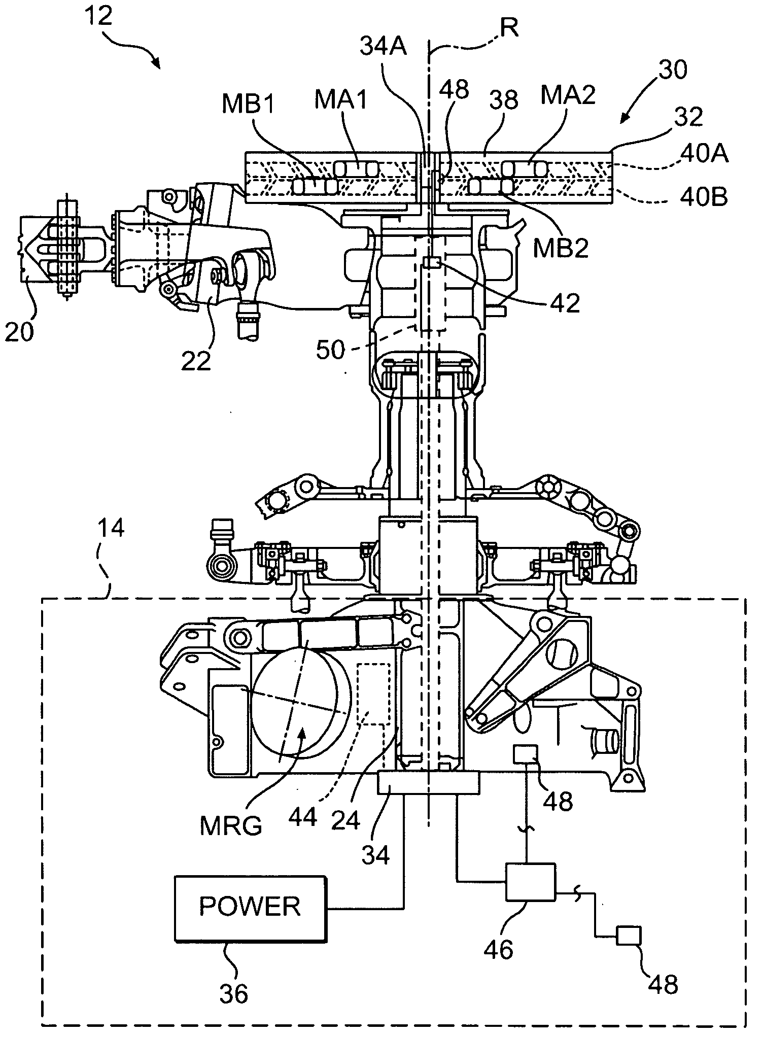
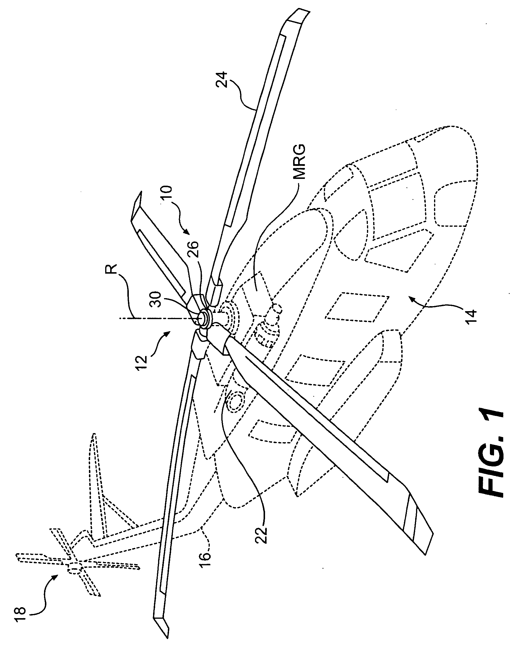
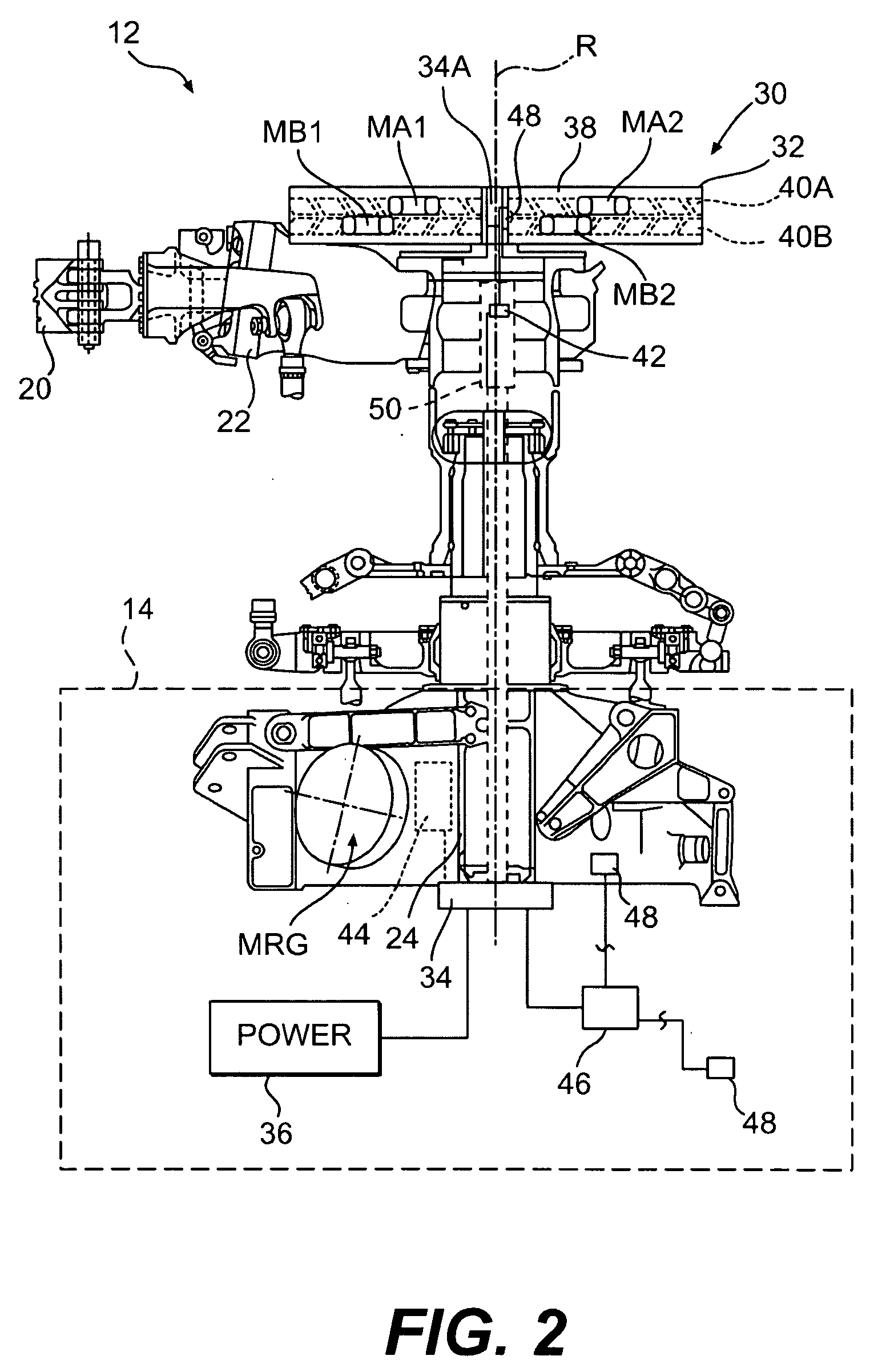
[0031]FIG. 1 schematically illustrates a rotary-wing aircraft 10 having a main rotor system 12. The aircraft 10 includes an airframe 14 having an extended tail 16 which mounts an anti-torque system such as a tail rotor system 18. The main rotor assembly 12 is driven about an axis of rotation R through a main rotor gearbox (illustrated schematically at MRG) which is powered by one or more engines E. The main rotor system 12 includes a multiple of rotor blades 20 mounted to a rotor hub 22. The rotor hub 22 is driven about the axis of rotation R by a main rotor shaft 24 which is driven by the main rotor gearbox MRG. Although a particular helicopter configuration is illustrated and described in the disclosed non-limiting embodiment, other configurations and / or machines, such as high speed compound rotary wing aircraft with supplemental translational thrust systems, dual contra-rotating, coaxial rotor system aircraft, turbo-props, tilt-rotors and tilt-wing aircraft, will also benefit her...


PUM


Abstract

A vibration suppressor system includes an annular electric motor system which independently controls rotation of at least two masses about the axis of rotation to reduce in-plane vibration of the rotating system. A method of reducing vibrations in a rotary-wing aircraft includes independently controlling a relative angular position of a multiple of independently rotatable masses to reduce vibrations of a main rotor system.

Description

BACKGROUND OF THE INVENTION[0001]The present application claims priority to U.S. Provisional Patent Application Ser. No. 61 / 070097, filed Mar. 20, 2008.[0002]The present invention relates to a vibration suppressor system.[0003]Vibration suppression is often utilized to null vibrations associated with a rotating system. Such vibrations, when left unattenuated may lead to crew and structural fatigue and premature failure of system components. The vibrations may also be transmitted through adjacent support structure to other areas and systems remote from the vibration source. Consequently, it may be desirable to suppress these vibrations proximal the vibration source.[0004]One application which exemplifies vibration isolation / absorption is the main rotor system of a rotary-wing aircraft. Typically, the main rotor system includes a hub system which drives a plurality of rotor blades subject to a variety of aerodynamic and gyroscopic loads. For example, as each rotor blade advances or re...

Claims


Application Information

Patent Timeline
IPC IPC(8): B64C27/51G01M1/38H02K41/03F04D29/26H02K5/24G05B13/00F16F15/36F16F15/10
CPCB64C27/001B64C2027/003F16F15/223G01M1/36H02K7/04H02K7/14Y10T74/2121H02K41/025F01D5/02F16F7/1011H02P5/526Y10T74/2127H02K16/02H02P5/56
Inventor WELSH, WILLIAM A.
Owner SIKORSKY AIRCRAFT CORP
Why Eureka
Try Eureka