

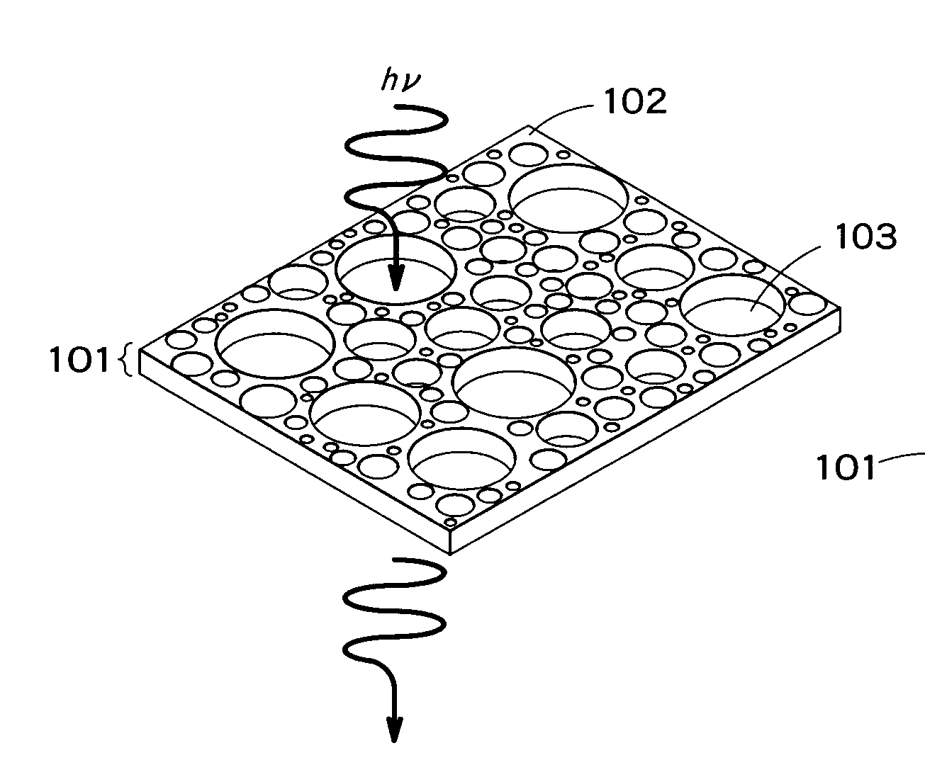
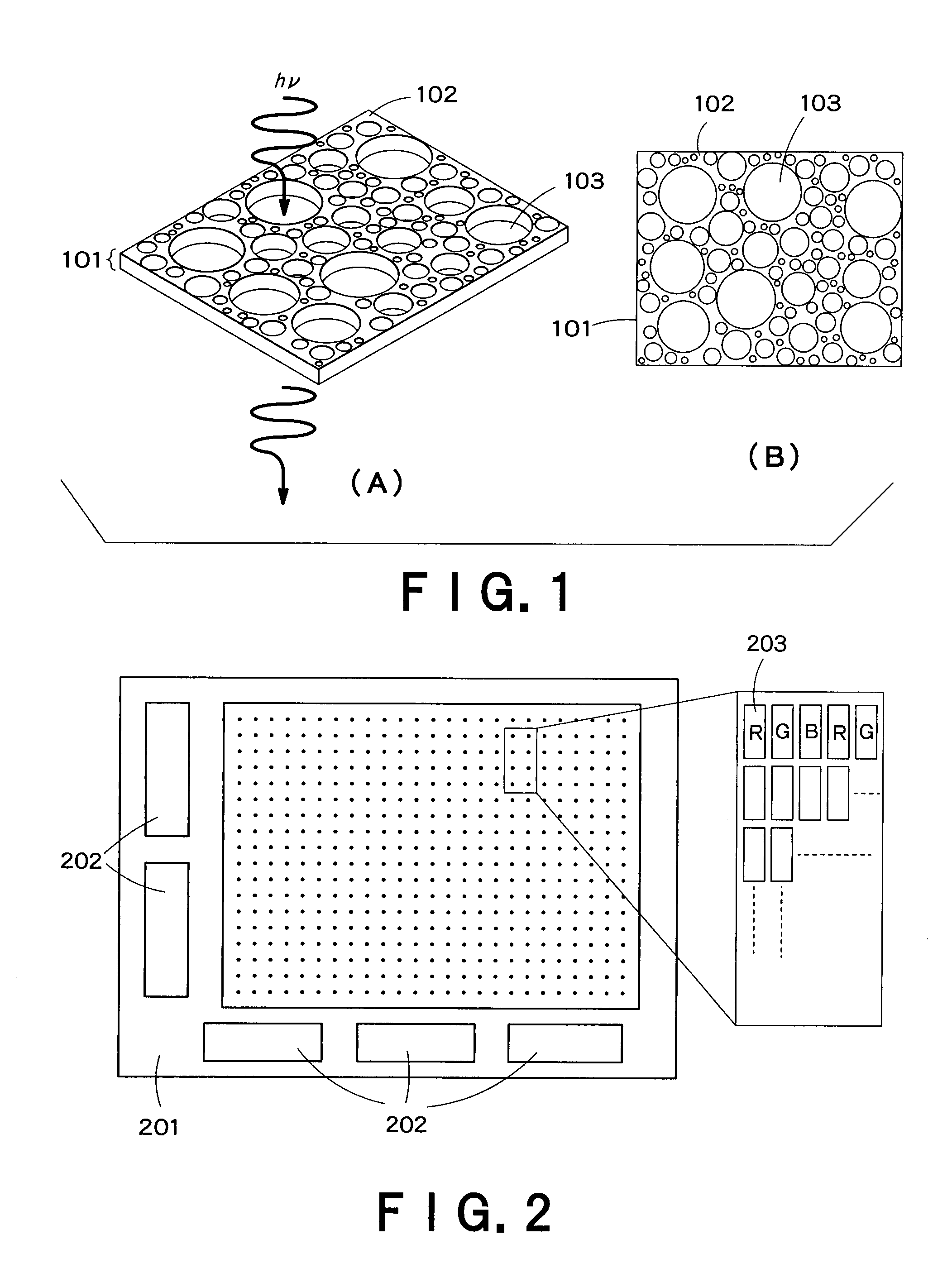
Displaying device and lighting device employing organic electroluminescence element
a technology of lighting device and electroluminescence element, which is applied in the direction of non-electron-emitting shielding screen, tubes with electrostatic control, etc., can solve the problems of affecting the future exhaustion of electricity, difficult to adopt an ito electrode in the top emission type, and difficult to achieve the effect of el lighting device emitted light evenly from the whole surface, etc., and achieves the effect of effectively inhibiting and not particularly restricting the opening shap
- Summary
- Abstract
- Description
- Claims
- Application Information
AI Technical Summary
Benefits of technology
Problems solved by technology
Method used
Image

Examples
example 1
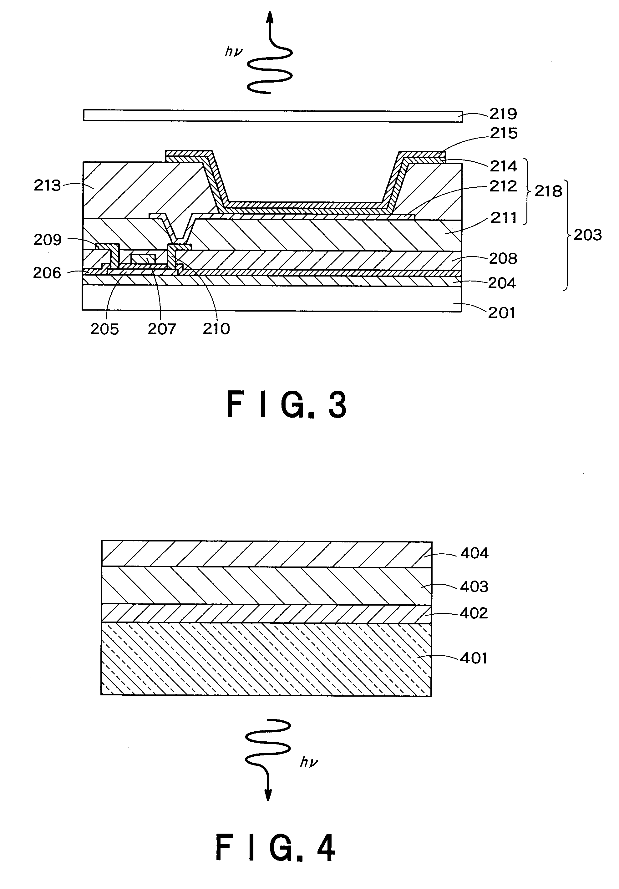
[0156]On a glass substrate, SiO2 and SiN were deposited by the plasma CVD method in thicknesses of 100 nm and 50 nm, respectively, to prepare an undercoating layer. Successively, amorphous silicon was deposited by the plasma CVD method in 50 nm thickness to form a semiconductor layer. After subjected to dehydrogenation annealing, the semiconductor layer was irradiated with excimer laser beams to crystallize the amorphous silicon and thereby to from polysilicon on the area where TFT was to be provided. The area was then dry-etched by photolithography to pattern the polysilicon. Thereafter, SiO2 was deposited to form a gate-insulating layer, and MoW was deposited thereon. The deposited layer was subjected to patterning, to form a gate electrode. After doping, SiO2 was deposited by the plasma CVD method to form an interlayer dielectrics layer. Contact holes to the source area and the drain area were formed by photolithography, and then a source electrode 209 and a drain electrode 210, ...
example 2
[0159]The procedures of Example 1 were repeated to form layers of the display up to the organic layer. After that, MgAg alloy was co-deposited by vacuum deposition at the deposition rate of 10:1 to prepare a MgAg alloy layer of 5 nm thickness. Thereafter, a positive-type photoresist (THMR IP3250 [trademark], manufactured by Tokyo Ohka Kogyou Co., Ltd.) was spin-coated to form a resist layer of 80 nm thickness, and then an organic spin-on glass (SOG) composition (OCD-T7 5500-T [trademark], manufactured by Tokyo Ohka Kogyou Co., Ltd.) was coated and baked to form a SOG layer of 20 nm thickness. Further, a block polymer composed of polystyrene (PS) (Mw: 78000):polymethylmethacrylate (PMMA) (Mw: 170000) and PMMA (Mw: 1500) were mixed in the weight ratio of 6:4 to prepare a polymer solution, which was then coated and annealed so that the phase-separation pattern of the block polymer was generated.
[0160]The phase-separated pattern was dry-etched by oxygen gas, to remove the PMMA phase. Th...
example 3
[0161]The procedures of Example 1 were repeated to form layers of the display up to the organic layer. After that, MgAg alloy was co-deposited by vacuum deposition at the deposition rate of 10:1 to prepare a MgAg alloy layer of 30 nm thickness. Thereafter, a positive-type photoresist (THMR IP3250 [trademark], manufactured by Tokyo Ohka Kogyou Co., Ltd.) was coated and baked to form a resist layer of 80 nm thickness, and then an organic spin-on glass (SOG) composition (OCD-T7 5500-T [trademark], manufactured by Tokyo Ohka Kogyou Co., Ltd.) was coated and baked to form a SOG layer of 20 nm thickness. Further, a block polymer composed of polystyrene (PS) (Mw: 78000):polymethylmethacrylate (PMMA) (Mw: 170000) and PMMA (Mw: 1500) were mixed in the weight ratio of 6:4 to prepare a polymer solution, which was then coated and annealed so that the phase-separation pattern of the block polymer was generated. The phase-separated pattern was dry-etched by oxygen gas, to remove the PMMA phase. T...
PUM
 Abstract
Description
Claims
Application Information