[0061]The present invention is aimed to reduce scattering effects and thereby to improve the efficiency of straightforwardness of light, and hence it is necessary to treat sizes perturbing the incident light as parameters when the
surface structure is defined. From this viewpoint, it is found that the
diameter of the opening is most properly determined by the
radius of
gyration of the opening structure and thereby that the efficiency of straightforwardness of light can be most properly represented. That is to say, the
radius of the opening in the
surface structure according to the present invention is defined as its
radius of
gyration, and accordingly the
diameter is double the
radius of gyration. Even if the openings have different shapes, the same effect of the invention can be obtained as long as the radii of
gyration are the same.
[0062]In the present invention, the
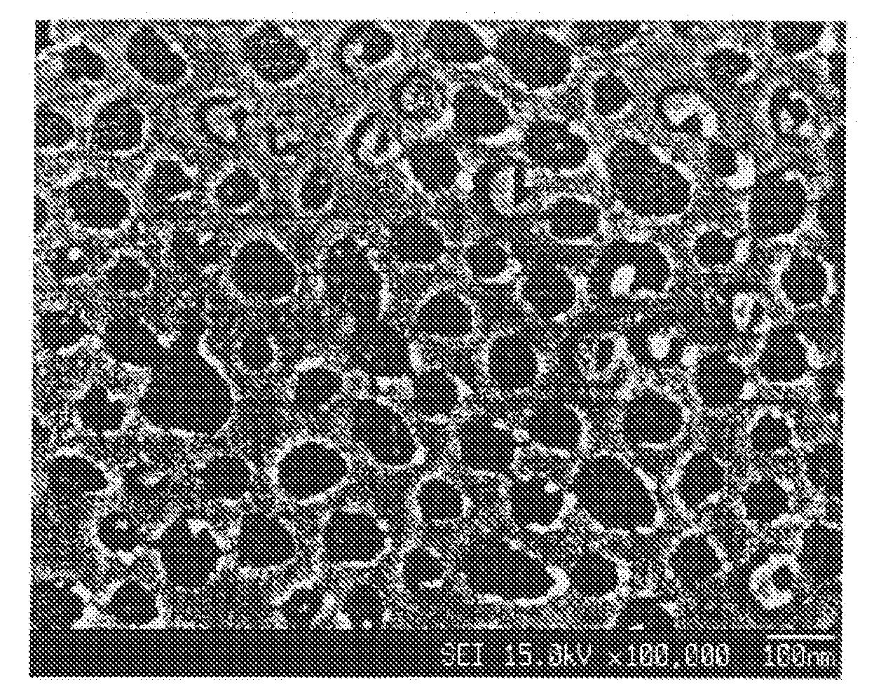
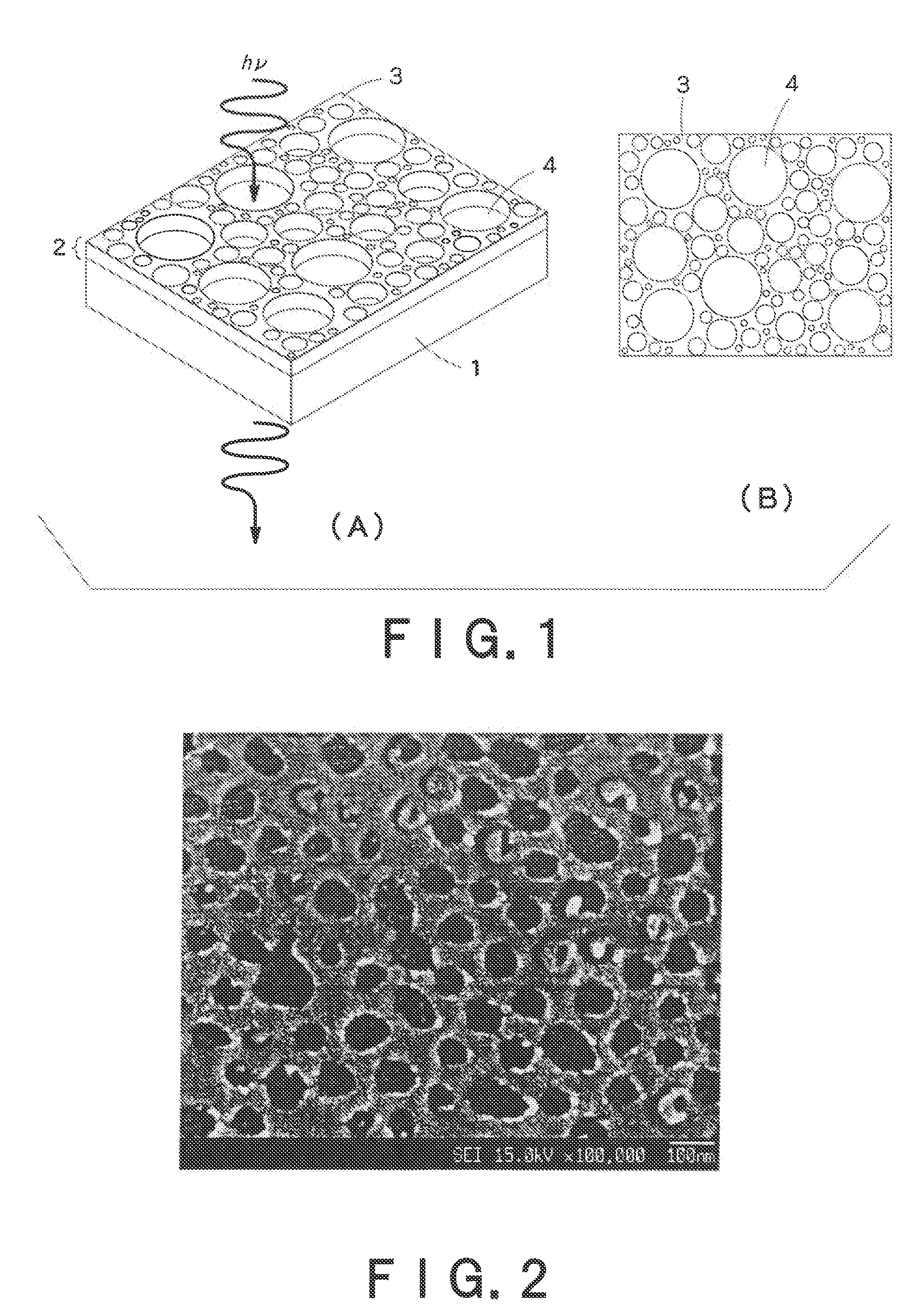
radius of gyration of the opening is defined as follows. On an image of the opening, circular lines at equal intervals are drawn from the edge. In concrete, on a relief image obtained by
atomic force microscopy, circular lines at equal intervals are drawn from the edge. The thus-obtained lines are image-processed to obtain the center of gravity. The distance from the center of gravity to the concavity is then determined, and is processed together with the moment to calculate the
radius of gyration R. The radius of gyration can be also obtained by
Fourier transform of the
electron or atomic force
micrograph.
[0063]The larger the
surface structure is, the more light is scattered. The effect of light-scattering is in proportion to the square of the size. Accordingly, the average radius of gyration R of the openings is preferably not more than ⅙ of the wavelength of incident light. That is to say, the
average diameter of the openings is preferably not more than ⅓ of the wavelength of incident light. If the average radius of gyration R is larger than that,
Rayleigh scattering is liable to occur and the light immediately loses straightforwardness. The
diameter of the openings is more preferably not more than ⅕, further preferably not more than 1 / 10 of the wavelength of light. As long as the above conditions are satisfied, the shapes of the openings are not particularly restricted. Examples of the opening shapes include cylindrical shape, conical shape, triangular pyramidal shape,
quadrilateral pyramidal shape, and other columnar or pyramidal shapes. And two or more shapes may be mixed. Even if the light-transmitting metal electrode according to the present invention contains various sizes of openings, the effect of the invention can be obtained. It is, on the contrary, rather preferred that the openings have various sizes because the metal part with those openings is apt to continue linearly in a relatively short straight length. In the case like the above, where the openings have various sizes, the diameters of the openings can be represented by the average.
[0064]
Diffraction of light incident on the light-transmitting metal electrode according to the present invention is then described below. When light penetrates from the transparent substrate-side to the metal layer-side, the scalar theory tells us as follows. On the assumption that the metal layer-side is regarded as an
air layer and that the electrode is regarded as a linear
diffraction grating, the condition for causing
diffraction is expressed by the following formula (2):sin θm−n sin θ1=m×λ / d (2)wherein
[0065]θm is an emission angle, θ1 is an incident angle on the transparent substrate-side, λ is a wavelength of incident light, d is an interval of
diffraction grating, m is a
diffraction order of integer (m=0, ±1, ±2 . . . ), and n is a
refractive index of the transparent substrate. Accordingly, the condition for not causing diffraction is that the formula (2) does not have a solution when the
diffraction order is the minimum: m=−1. This means that the condition is λ / n<1, and hence the ratio of the wavelength of light per the
refractive index of the transparent substrate is the threshold. The
refractive index of transparent substrate used generally is not more than 2.0, and therefore the diffraction can be avoided if the openings in the present invention are arranged at such intervals that pitches between the centers of the openings are not more than ½ of the wavelength of incident light.
[0066]Preferably, the relative positions of the openings are arranged at random, namely, isometrically. According to the first theoretical basis, the reason for this can be explained as follows. For example, if the openings are arranged in hexagonal symmetry, the metal part has areas periodically continued in tri-axial directions and therefore it is thought that the openings cannot inhibit the movement of free electrons isometrically.

