Apparatus, system, and method for an adaptive high efficiency switching power supply

a technology of switching power supply and high efficiency, applied in the field of power supply, can solve the problems of less than 80% efficiency and no cost-effective means for satisfactorily meeting efficiency requirements in the conventional art, and achieve the effect of improving efficiency

Active Publication Date: 2009-09-24
IBM CORP
View PDF4 Cites 55 Cited by
  • Summary
  • Abstract
  • Description
  • Claims
  • Application Information

AI Technical Summary

Benefits of technology

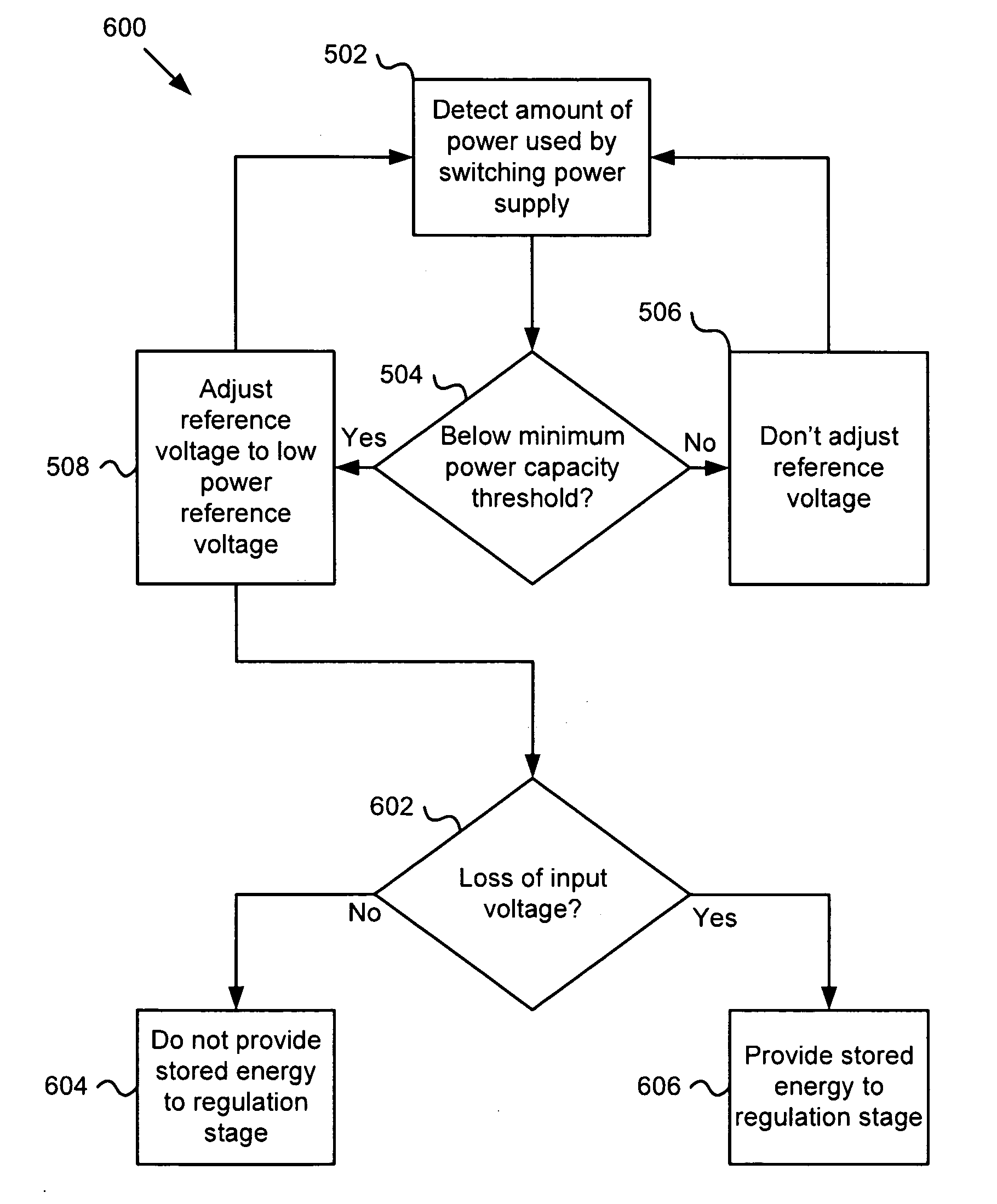
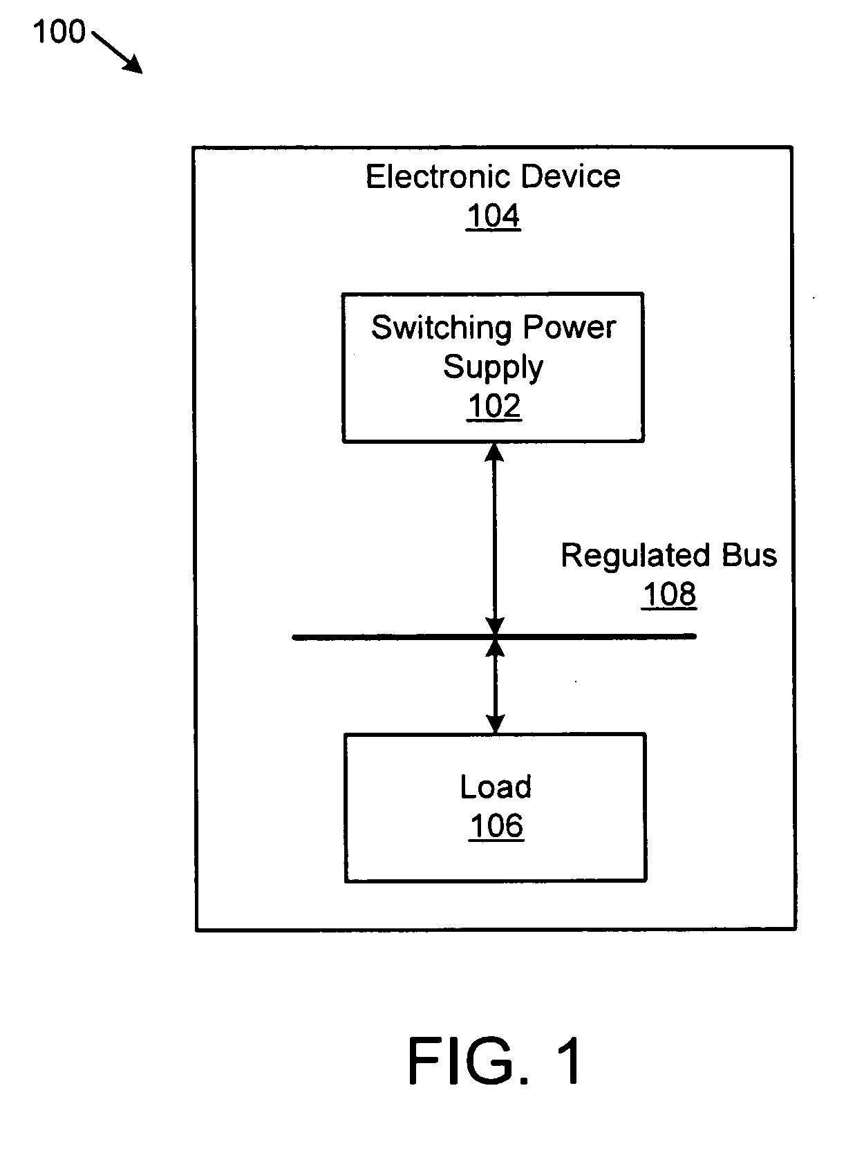
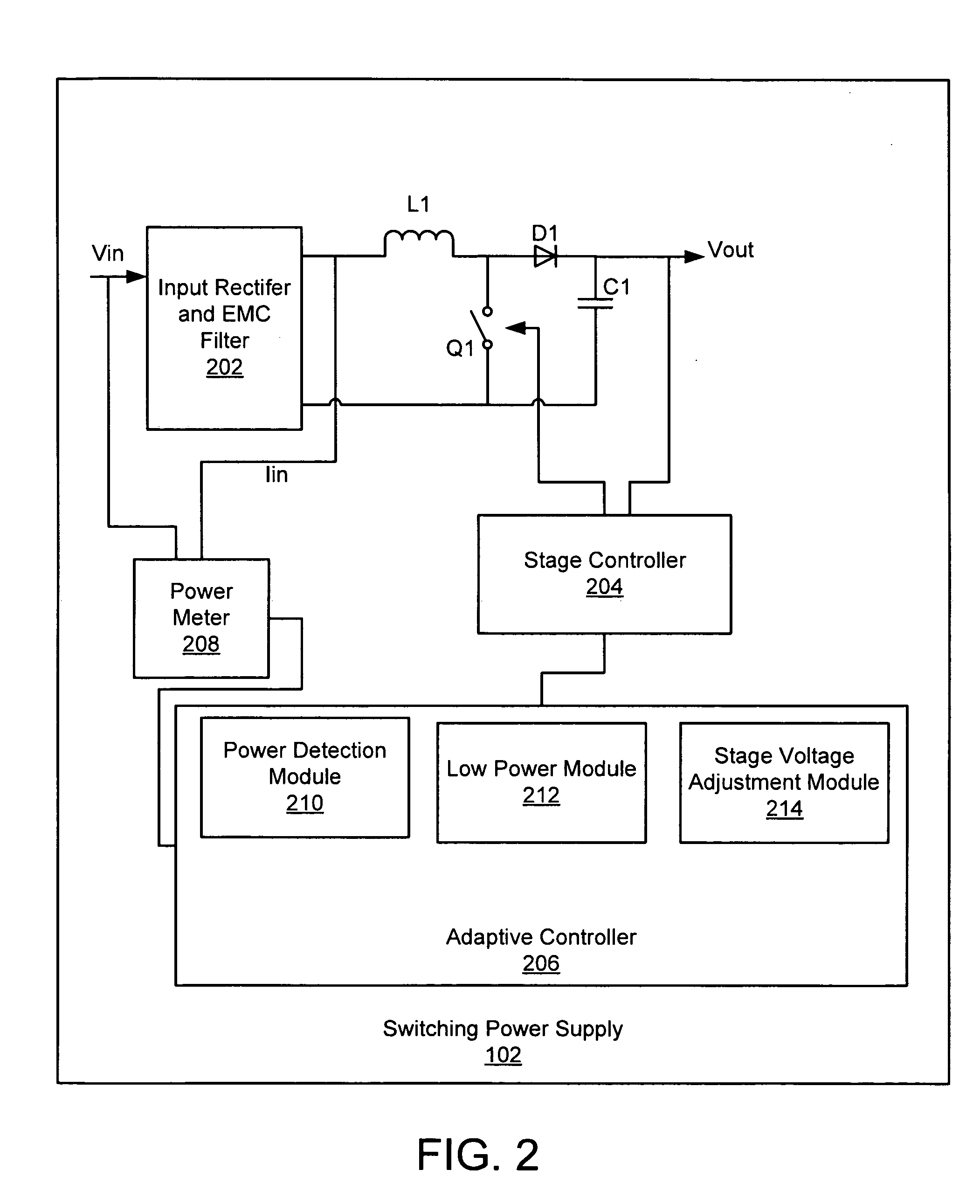
[0018]The power detection module detects an amount of power used by a switching power supply, and the switching power supply preferably includes a regulation stage with a stage controller that operates to regulate a voltage of the regulation stage relative to a reference voltage. The low power module determines if the amount of power used by the switching power supply is below a minimum power capacity threshold. The stage voltage adjustment module adjusts the reference voltage from a high power reference voltage to a low power reference voltage in response to the low power module determining that the amount of power used by the power supply is below the minimum power capacity threshold. The low power reference voltage causes a regulated voltage adjustment such that the switching power supply operates more efficiently below the minimum power threshold than if the reference voltage remained at the high power reference voltage during operation below the minimum power threshold.

Problems solved by technology

However, in a typical switching power supply this may result in an efficiency of less than 80% when operating at a 20% load.
However, none of the conventional art currently available has provided a cost effective means for satisfactorily meeting efficiency requirements when operating at lower loads.

Method used


Image

  • Apparatus, system, and method for an adaptive high efficiency switching power supply
  • Apparatus, system, and method for an adaptive high efficiency switching power supply
  • Apparatus, system, and method for an adaptive high efficiency switching power supply

Examples


Embodiment Construction

[0033]Many of the functional units described in this specification have been labeled as modules, in order to more particularly emphasize their implementation independence. For example, a module may be implemented as a hardware circuit comprising custom VLSI circuits or gate arrays, off-the-shelf semiconductors such as logic chips, transistors, or other discrete components. A module may also be implemented in programmable hardware devices such as field programmable gate arrays, programmable array logic, programmable logic devices or the like.

[0034]Modules may also be implemented in software for execution by various types of processors. An identified module of executable code may, for instance, comprise one or more physical or logical blocks of computer instructions which may, for instance, be organized as an object, procedure, or function. Nevertheless, the executables of an identified module need not be physically located together, but may comprise disparate instructions stored in d...


PUM


Abstract

An apparatus, system, and method are disclosed for an adaptive high efficiency switching power supply. The switching power supply has a regulation stage with a stage controller that operates to regulate a voltage of the regulation stage relative to a reference voltage. A power detection module detects an amount of power used by the switching power supply. A low power module determines if the power supply is operating below a minimum power capacity threshold. A stage voltage adjustment module adjusts the reference voltage from a high power reference voltage to a low power reference voltage in response to the low power module determining that the power supply is operating below the minimum power capacity threshold. The low power reference voltage causes a regulated voltage adjustment such that the switching power supply operates more efficiently below the minimum power threshold.

Description

BACKGROUND OF THE INVENTION[0001]1. Field of the Invention[0002]This invention relates to power supplies, and more particularly relates to adaptively increasing the efficiency of a switching power supply.[0003]2. Description of the Related Art[0004]A power supply, sometimes known as a power supply unit or PSU, is a device or system that supplies electrical or other types of energy to an output load or group of loads. A power supply, in some embodiments may be configured to convert power in one form to another form, such as converting AC power to DC power. The regulation of power supplies is typically done by incorporating feedback and control circuitry to tightly control the output voltage or current of the power supply to a specific value. The specific value is closely maintained despite variations in the load presented to the power supply's output, or any reasonable voltage variation at the power supply's input. A switching power supply is a power supply that incorporates a switch...

Claims


Application Information

Patent Timeline
Patent Type & Authority Applications(United States)
IPC IPC(8): G05F1/00
CPCH02M3/156Y02B70/16H02M2001/0032H02M2001/0025H02M1/0025H02M1/0032Y02B70/10
Inventor DISHMAN, CECIL C.MALIK, RANDHIR S.
Owner IBM CORP
Why Eureka
Try Eureka