System and method for using MEMS filter bank

a micro-electromechanical system and filter bank technology, applied in the direction of electrical equipment, transmission, electromechanical/electrostrictive/magnetostrictive devices, etc., can solve the problems of ineffective filters, ineffective high-frequency signals, and ineffective theories, so as to reduce interference in incoming signals.

Active Publication Date: 2009-09-24
GENERAL DYNAMICS MISSION SYST INC
View PDF18 Cites 5 Cited by
  • Summary
  • Abstract
  • Description
  • Claims
  • Application Information

AI Technical Summary

Benefits of technology

[0018]According to still yet another embodiment of the invention, an apparatus for reducing interference in an incoming signal traveling along a signal pathway is provide. The apparatus includes a plurality of banks MEMS resonators, and a plurality of amplifiers each located downstream of a respective bank of MEMS resonators. The output of each amplifier is connected to an available downstream one of the plurality of banks of MEMS resonators to thereby iteratively process the signal. A controller is configured to receive the signal and the output of each amplifier, and to issue control signals to individual MEMS resonators with the plurality of banks of MEMS resonators, to thereby attenuate interference components with the incoming signal. The a signal of interest will be recoverable from either the incoming signal or the output of at least one of the amplifiers.

Problems solved by technology

Antennas often receive radio frequency transmissions that include both a desired signal and substantial undesirable interference in adjacent frequencies.
The challenge is to recover a desired weak signal that is proximate to stronger interference signals.
However, such efforts have not proven effective for high frequency signals, as the bandwidth of the signal (typically on the order of 10,000 Hz) is much larger than the bandwidth of typical band pass filters (typically on the order of 500 Hz). FIG. 2 shows an example of the signals from FIG. 1 being filtered according to this method.
Such filters may also prove ineffective if there are any desirable signals that fall outside of the range of the filter.
The theory has not proven effective in practice because of a lack of stability in MEMS resonators.
However, the specific resonance frequency of a MEMS filter is also highly dependent on the shape of the components, which is subject to variances in manufacturing accuracy and tolerance during initial fabrication.
Another drawback of the use of MEMS filters in this manner is that the filter processes the desired signal.
Still another drawback of the use of MEMS filters in this manner is that because the signal of interest tends to be much smaller than the noise, it may be difficult to find the signal of interest if its specific frequency is not known.

Method used


Image

  • System and method for using MEMS filter bank
  • System and method for using MEMS filter bank
  • System and method for using MEMS filter bank

Examples


Embodiment Construction

[0036]The particulars shown herein are by way of example and for purposes of illustrative discussion of the exemplary embodiments of the present invention only and are presented in the cause of providing what is believed to be the most useful and readily understood description of the principles and conceptual aspects of the present invention. In this regard, no attempt is made to show structural details of the present invention in more detail than is necessary for the fundamental understanding of the present invention, the description taken with the drawings making apparent to those skilled in the art how the several forms of the present invention may be embodied in practice.

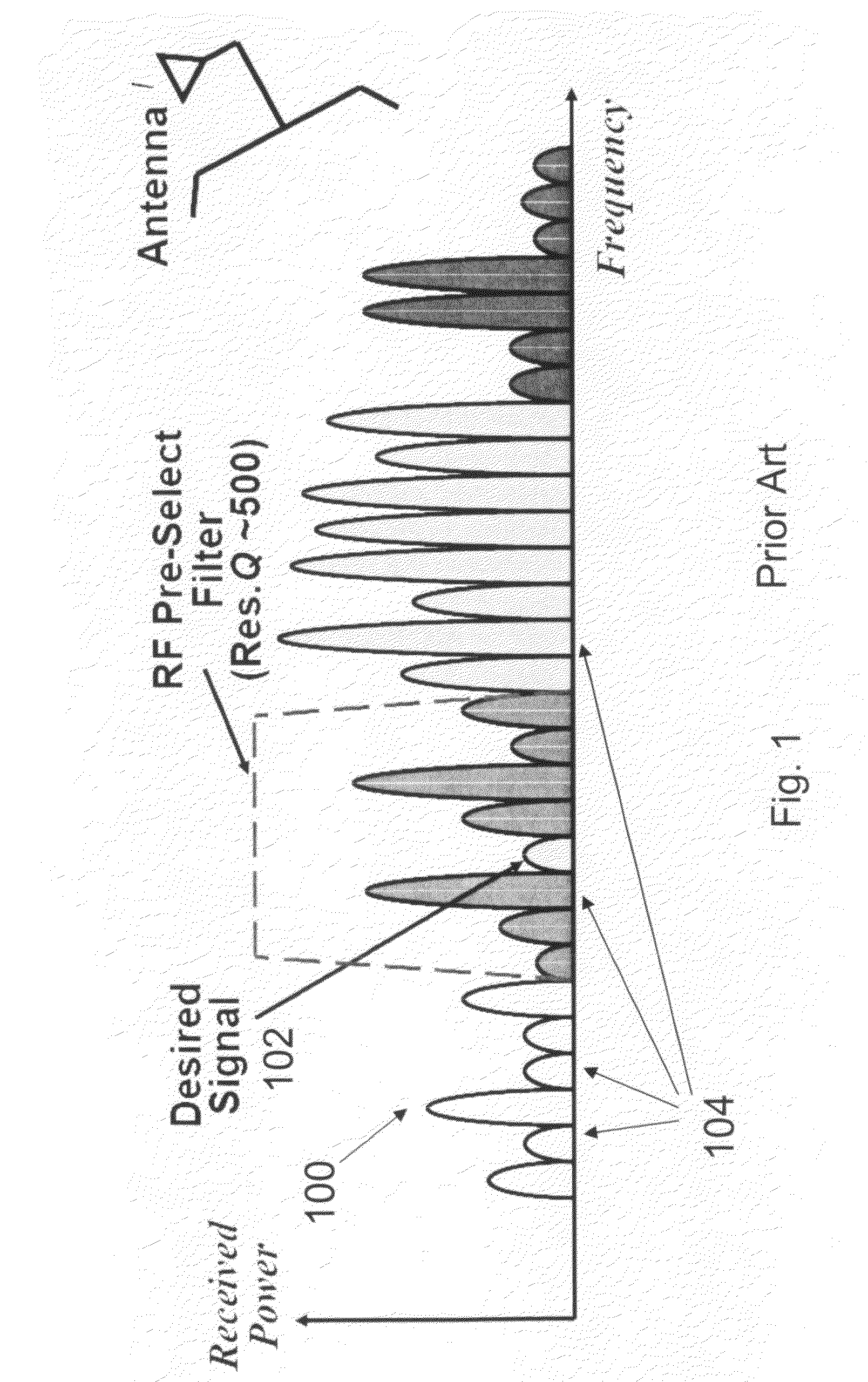
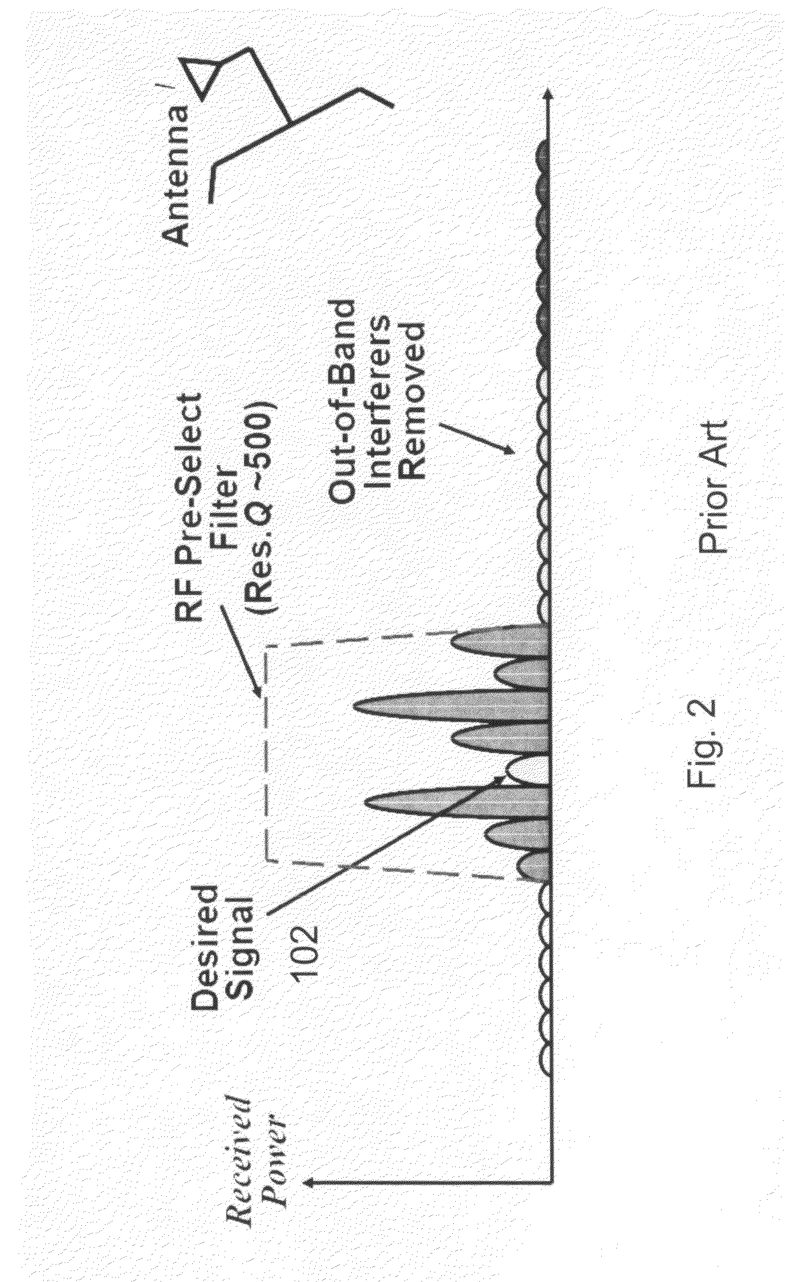
[0037]Referring again to FIG. 1, embodiments of the invention will receive a signal 100 that includes at least one signal of interest 102, as well as various noise signals 104 at different frequencies from the signal of interest 102. Except where indicated, for ease of explanation reference will be made to only ...


PUM


Abstract

A method and apparatus for recovering at least one signal of interest are provided. The method includes receiving an overall signal, the overall signal including the at least one signal of interest and a plurality of other signals, identifying at least one of the strongest components of the plurality of other signals, attenuating, using at least one MEMS resonator, any of the components identified by the identifying, wherein the overall signal will be modified to include the at least one signal of interest, attenuated versions of the components identified by the identifying, and the remaining portions of the plurality of other signals that were not subject to the attenuating, and recovering, after the attenuating, the at least one signal of interest.

Description

CROSS REFERENCE TO RELATED APPLICATIONS[0001]The instant application claims priority to U.S. Provisional Application 60 / 996,937 filed on Dec. 11, 2007, which is incorporated by reference herein in its entirety.BACKGROUND OF THE INVENTION[0002]1. Field of the Invention[0003]The present invention relates to reducing the presence of interference with a desired signal. More specifically, the present invention relates to the use of micro-electromechanical systems (“MEMS”) filters to reduce the presence of interfering signals in the same frequency range of desired signals.[0004]2. Discussion of Background Information[0005]Antennas often receive radio frequency transmissions that include both a desired signal and substantial undesirable interference in adjacent frequencies. Since signal strength and amplitude is directly related to the distance of the signal source to the antenna, the desired signal (which typically emanates from a distant signal source) may be much weaker than interferenc...

Claims


Application Information

Patent Timeline
Patent Type & Authority Applications(United States)
IPC IPC(8): H03H9/46
CPCH03H9/2447H03H9/465H03H9/462
Inventor CHEN, TING-YIN
Owner GENERAL DYNAMICS MISSION SYST INC
Why Eureka
Try Eureka