
Camera, storage medium having stored therein camera control program, and camera control method

Active Publication Date: 2009-09-24
CASIO COMPUTER CO LTD
View PDF90 Cites 34 Cited by
  • Summary
  • Abstract
  • Description
  • Claims
  • Application Information

AI Technical Summary

Benefits of technology

[0012]According to the present invention, since a prescribed identifier is displayed at a position on the graph corresponding to photography conditions that correspond to the determined photographic scene, it is possible for the user easily to set photography conditions manually with reference to a position of the identifier displayed. Therefore, it is possible to solve the demerits of both the fully automatic camera and the manual camera, and there is the advantage of being able to resolve the disadvantages of inconveniencing the user with a configuration operation of photography conditions while reflecting the intention of the user in the photography conditions.

Problems solved by technology

However, for fully automatic cameras, while it is possible for a user to perform photography and recording with appropriate photography conditions according to the photographic scene without being inconvenienced with configuration operations for photography conditions, as mentioned above, the intention of the user is entirely unreflected in the photography conditions.
Therefore, a demerit arises in that attributes that directly reflect the intention of the user are not imparted to the recorded image at all.
However, with the manual camera, since the user himself or herself must assess the photographic scene and manually configure all photography conditions, even though the user's intention is directly reflected in the recorded image, a demerit arises in that the user is inconvenienced with a configuration operation of the photography conditions.

Method used


Image

  • Camera, storage medium having stored therein camera control program, and camera control method
  • Camera, storage medium having stored therein camera control program, and camera control method
  • Camera, storage medium having stored therein camera control program, and camera control method

Examples


Embodiment Construction

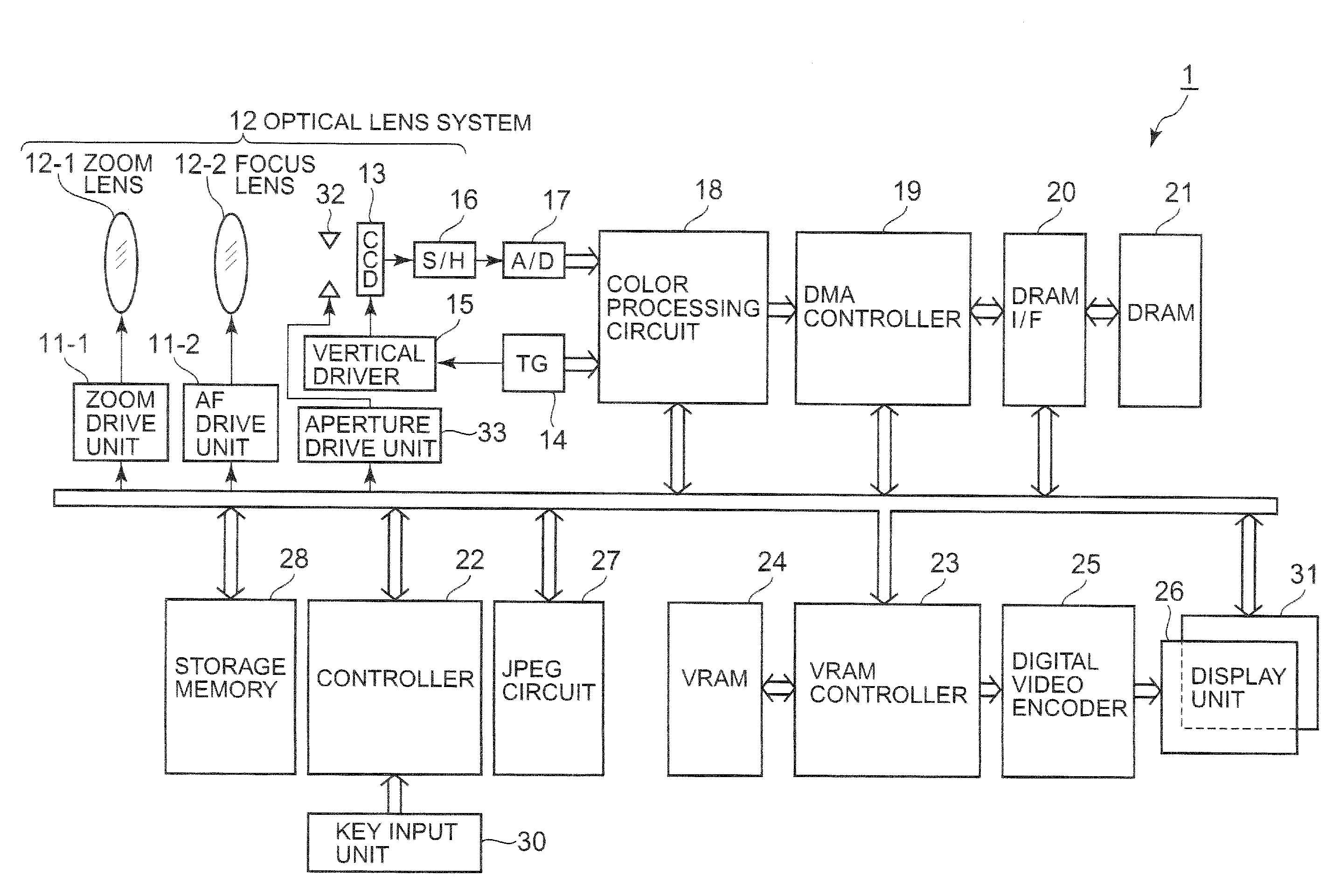
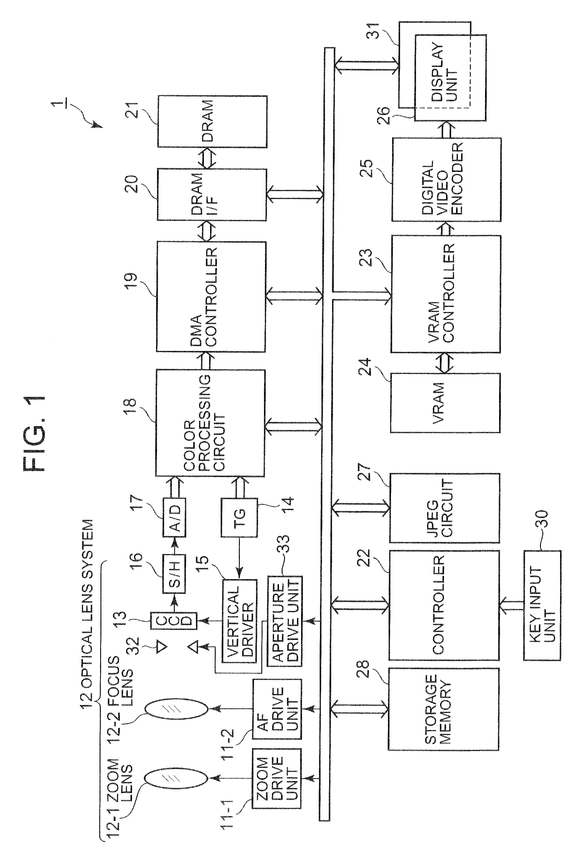
[0022]Hereinafter, an embodiment of the present invention is described with reference to the diagrams. FIG. 1 is a diagram showing an electronic circuit structure of a digital camera 1 according to an embodiment of the present invention. This digital camera 1 includes a zoom drive unit 11-1 for causing a zoom lens 12-l to move and perform an optical zoom action, and an AF drive unit 11-2 for causing a focus lens 12-2 to move and perform a focus action, in a photography mode, a lens optical system 12 constituting an imaging lens including the zoom lens 12-1 and the focus lens 12-2, an aperture 32 placed on an optical axis of the lens optical system 12, an aperture drive unit 33 for driving this aperture 32, a CCD 13 which is an imaging device, a timing generator (TG) 14, a vertical driver 15, a sample and hold circuit (S / H) 16, an analog-to-digital (A / D) converter 17, a color processing circuit 18, a DMA (Direct Memory Access) controller 19, a DRAM interface (I / F) 20, and DRAM 21. Fu...


PUM


Abstract

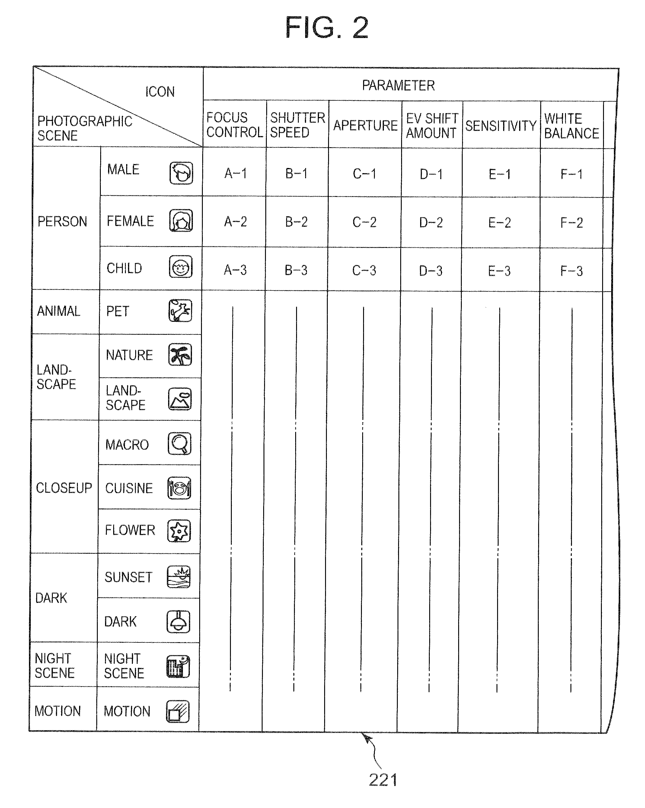
A graph 261, in which “aperture” is configured on the vertical axis, and “shutter speed” is configured on the horizontal axis, is displayed as superimposed on a through image. On this displayed graph 261, at a position of a parameter value corresponding to a determined photographic scene, an icon 262 of the photographic scene is displayed. When the icon 262 is operated and moved by a user, the display of the icon 262 is changed to a position on the graph 261 where the icon 262 is operated and moved, and values of the vertical axis and the horizontal axis are read off and the corresponding parameter stored in a RAM is updated. When the shutter key is operated, photographic processing is carried out with parameters stored in the RAM, and image data obtained by this photographic processing is recorded in the storage memory.

Description

[0001]This application is based on and claims the benefit of priority from Japanese Patent Application No. 2008-144083, filed on 2 Jun. 2008, the content of which is incorporated herein by reference.BACKGROUND OF THE INVENTION[0002]1. Field of the Invention[0003]The present invention relates to a camera, storage medium having stored therein camera control program, and camera control method for performing photography under set photography conditions.[0004]2. Related Art[0005]Conventionally, a so-called “fully automatic camera” that automatically sets photography conditions and performs photography has been proposed. For example, a full automatic camera disclosed in Japanese Unexamined Patent Application Publication No. 2008-11289 determines a photographic scene based on a subject image obtained from an imaging device, and automatically configures photography conditions (photography node) of the camera according to this determined photographic scene. Therefore, without being inconveni...

Claims


Application Information

Patent Timeline
IPC IPC(8): H04N5/222G03B7/00G03B17/02G03B17/18H04N5/225H04N5/232H04N101/00
CPCG03B7/00H04N5/23216H04N9/7921H04N5/23293H04N5/772H04N5/23245H04N23/62H04N23/667H04N23/631H04N23/00
Inventor WATANABE, MAKOTOMAGAKI, YOSUKENAKAZAWA, SACHIKOONUMATA, YUICHI
Owner CASIO COMPUTER CO LTD
Learn More