LED lighting device having heat convection and heat conduction effects and heat dissipating assembly therefor

a technology of led lighting and heat conduction, which is applied in the direction of lighting and heating equipment, semiconductor devices for light sources, and support devices for lighting, etc., can solve the problems of reduced heat dissipation efficiency, etc., and achieves high heat dissipation efficiency.

Inactive Publication Date: 2009-09-24
PAN JIT INT
View PDF4 Cites 57 Cited by
  • Summary
  • Abstract
  • Description
  • Claims
  • Application Information

AI Technical Summary

Benefits of technology

[0007]The main objective of the invention is to provide an LED lighting device with a heat-dissipating assembly providing high heat-dissipating efficiency with directional convection.
[0009]When the LED lighting device lights up, the exterior flue will continually force heated air to directionally move into the exterior flue due to the stack effect. The heating air will move into the housing and finally flow out via the air holes. With such continuous and directional air movement, the LED lighting device obtains good heat-dissipating efficiency.

Problems solved by technology

An LED lighting device lights up quickly, generates more light per watt than an incandescent lamp and has a relatively long life span.
Furthermore, an LED lighting device is difficult to damage with external shocks when compared with traditional fluorescent and incandescent bulbs.
When the LED lighting device is active in high surrounding temperatures overheating and device failure may occur.
Therefore, the LED lighting device requires sufficient heat dissipation to maintain a long life span.
However, low heat convection allows high-temperature air around the fins to lower a heat dissipating efficiency.

Method used


Image

  • LED lighting device having heat convection and heat conduction effects and heat dissipating assembly therefor
  • LED lighting device having heat convection and heat conduction effects and heat dissipating assembly therefor
  • LED lighting device having heat convection and heat conduction effects and heat dissipating assembly therefor

Examples


Embodiment Construction

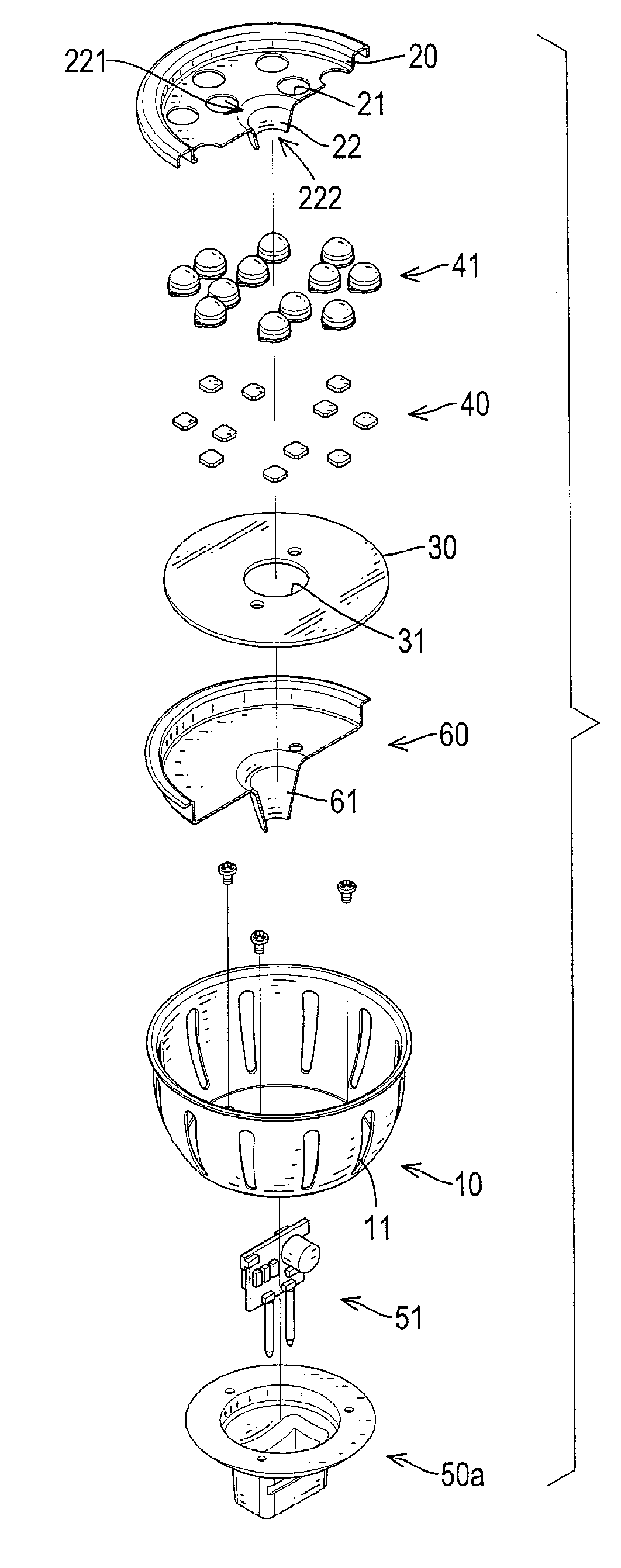
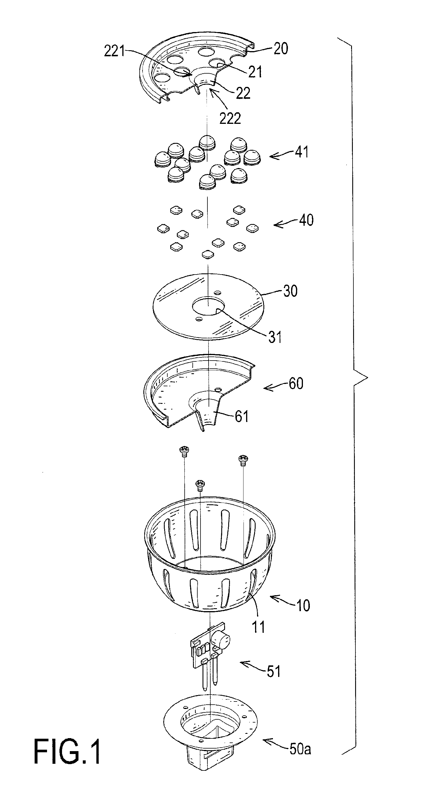
[0017]With reference to FIGS. 1, 2, 4, 5 and 6, an LED lighting device in accordance with the present invention comprises a heat dissipating assembly, a substrate (30), multiple LEDs (40), a base (50a, 50b) and may have a control module (51), a converter (70), a contact cap (71) and multiple condensers (80).

[0018]The heat dissipating assembly comprises a housing (10), an outer cover (20) and an optional inner cover (60).

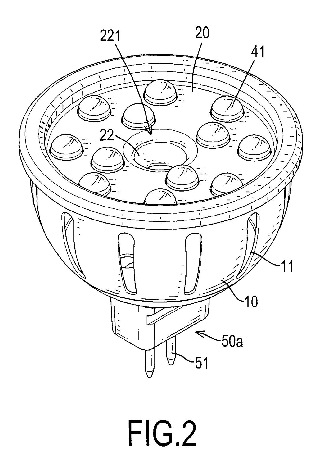
[0019]The housing (10) is heat conductive and has an open top, a bottom and multiple air holes (11) being formed through the housing (10) and may be bowl-shaped and metallic and may be made of aluminum.

[0020]The outer cover (20) is heat conductive and mounted on the open top of the housing (10) and has multiple through holes (21) and an exterior flue (22) and may be metallic and may be made of aluminum. The exterior flue (22) protrudes from the outer cover (20) and extends into the housing (10) and has an outer open end (221) and an inner open end (222). The outer op...


PUM


Abstract

An LED lighting device having heat convection and heat conduction effects has a heat dissipating assembly, a substrate, multiple LEDs and a base. The heat dissipating assembly has a housing and an outer cover. The housing has multiple air holes. The outer cover is mounted on an open top of the housing and has multiple through holes and an exterior flue protruding from the outer cover and extending into the housing. The substrate is mounted inside the housing against the outer cover and has a hole allowing the exterior flue to extend therethrough. The LEDs are mounted on the substrate and respectively correspond to the through holes. The base is attached to a bottom of the housing. The exterior flue encourages heated air to move through the exterior flue and flow out of the housing via the air holes. With such continuous and directional air movement, the LED lighting device obtains good heat-dissipating efficiency.

Description

BACKGROUND OF THE INVENTION[0001]1. Field of the Invention[0002]The present invention relates to an LED lighting device, especially to an LED lighting device with a heat-dissipating assembly providing high heat dissipating efficiency with directional convection.[0003]2. Description of the Related Art[0004]A Light-Emitting Diode (LED) is a semiconductor element that converts electricity into light and is often used as a light source. An LED lighting device lights up quickly, generates more light per watt than an incandescent lamp and has a relatively long life span. Furthermore, an LED lighting device is difficult to damage with external shocks when compared with traditional fluorescent and incandescent bulbs.[0005]Operating performance of an LED lighting device largely depends on a surrounding temperature. When the LED lighting device is active in high surrounding temperatures overheating and device failure may occur. Therefore, the LED lighting device requires sufficient heat dissi...

Claims


Application Information

Patent Timeline
Patent Type & Authority Applications(United States)
IPC IPC(8): F21V29/00F21V21/00F21S4/00F21V29/02
CPCF21Y2103/022F21K9/1375F21V29/83F21V29/507F21Y2101/02F21K9/23F21Y2103/33F21Y2115/10
Inventor LEE, TSU
Owner PAN JIT INT
Why Eureka
Try Eureka