Low-clearance light-emitting diode lighting
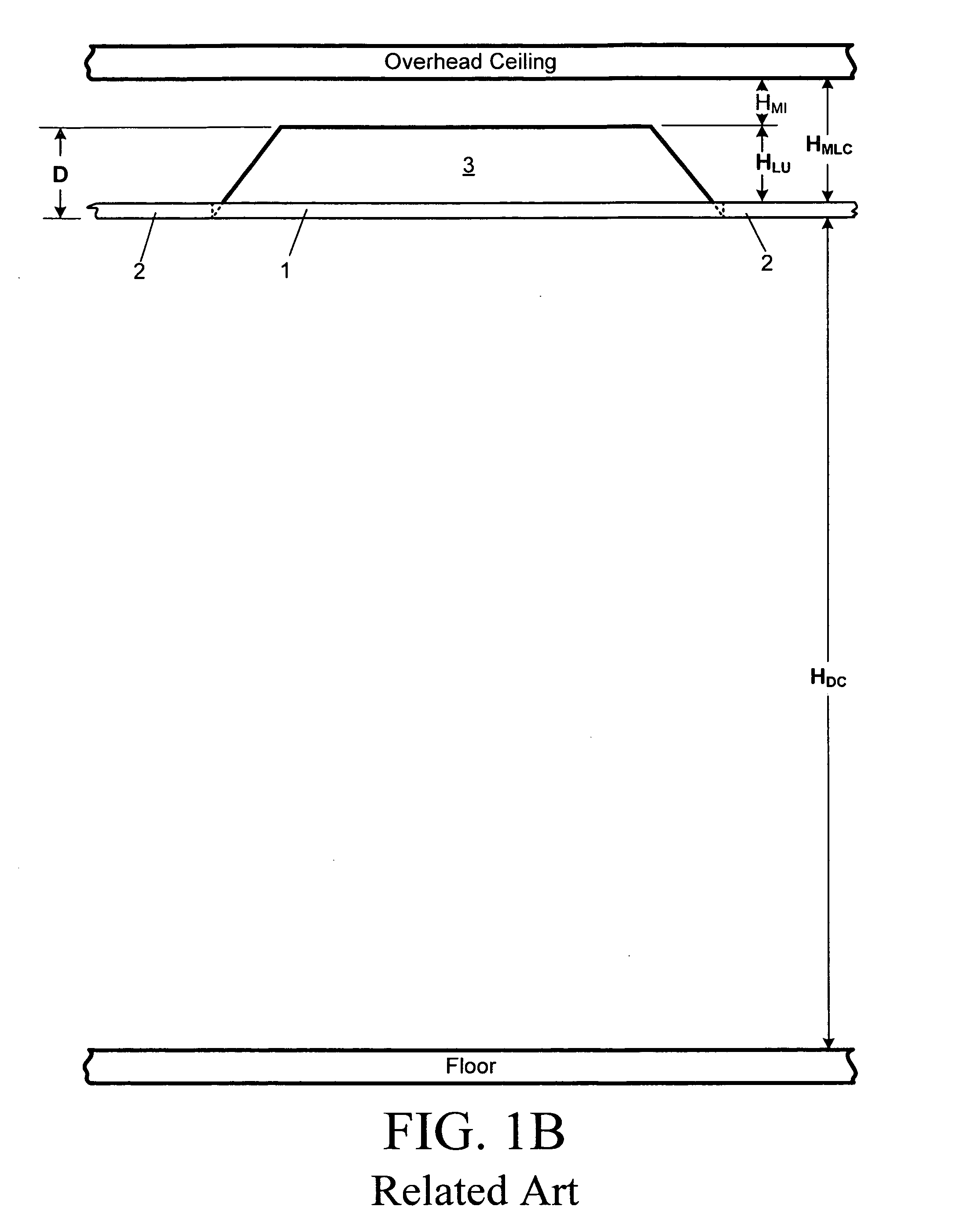
a light-emitting diode and low clearance technology, applied in the field of lighting, can solve the problems of limited hdc for the maximum drop-ceiling height, limited overhead ceiling clearance, and limited size of related art lighting units, so as to improve the thermal dissipation capability of light-emitting diode lighting and low overhead clearance
- Summary
- Abstract
- Description
- Claims
- Application Information
AI Technical Summary
Benefits of technology
Problems solved by technology
Method used
Image
Examples
first embodiment
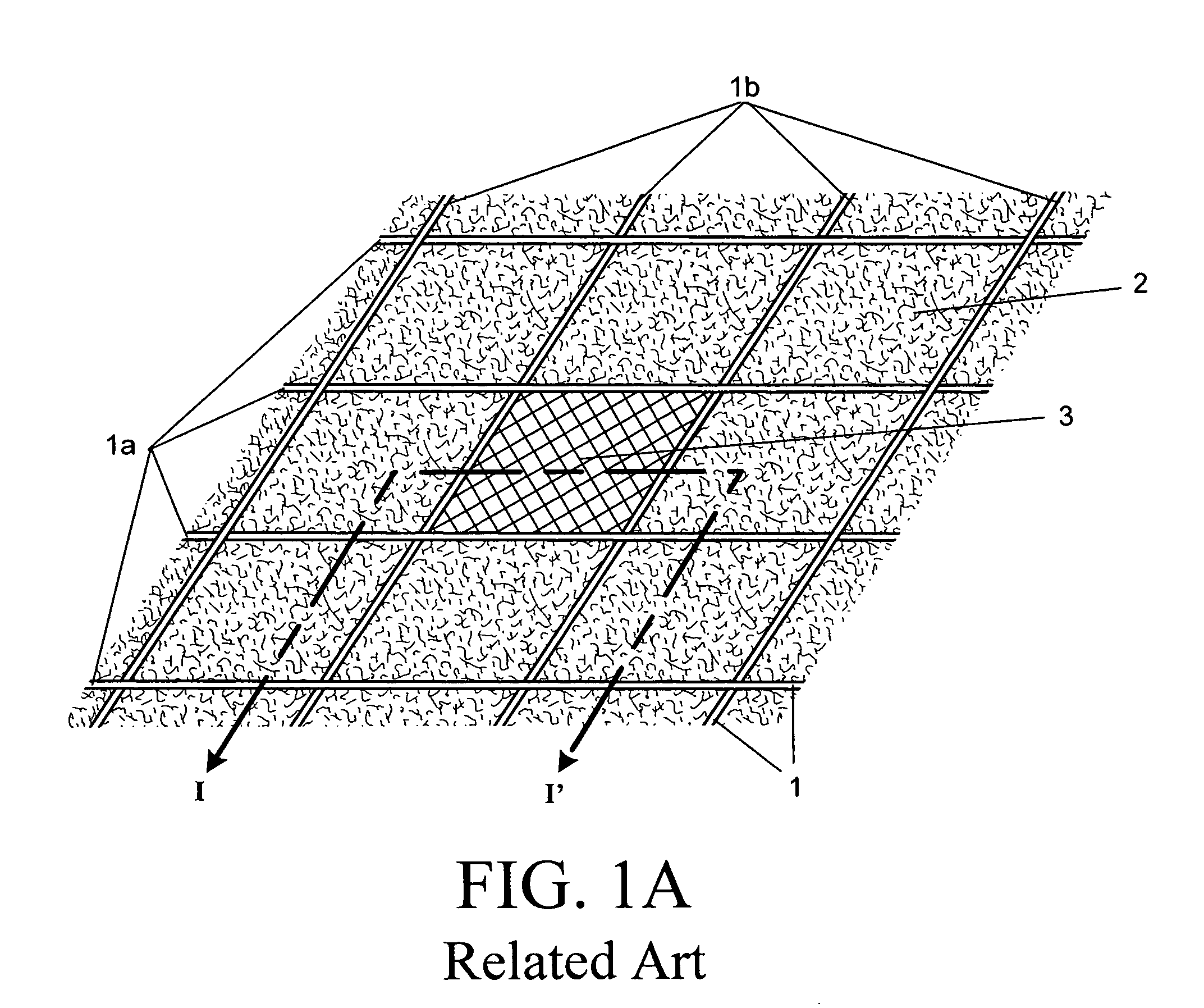
[0040]FIG. 2A is a perspective view of a ceiling-grid with a low-clearance light-emitting diode lighting unit according to the invention. As shown in FIG. 2A, horizontal rails 10a and vertical rails 10b create a ceiling-grid 10 having openings in which ceiling tiles 20 are positioned. The ceiling-grid 10 shown in FIG. 2A is, for example, a two foot by two foot ceiling-grid 10. As also shown in FIG. 2A, a low-clearance light-emitting diode lighting unit 30 is positioned in an opening of the ceiling-grid 10. The low-clearance light-emitting diode lighting unit 30 has a similar size or outside dimensions as the ceiling tiles 20. Although a two foot by two foot ceiling-grid 10 is shown in FIG. 2A, embodiments of the invention can be implemented in two foot by four foot grid as well as grids of other sizes.
[0041]FIG. 2B is a cross-sectional view of a ceiling-grid with a lighting unit along the line II-II′ of FIG. 2A. As shown in FIG. 2B, the low-clearance light-emitting diode lighting un...
second embodiment
[0050]FIG. 5A is a side view of the light tile shown in FIG. 3 according to the invention. As shown in FIG. 5, a low-clearance light-emitting diode lighting unit can include a light guide panel 38 for receiving light from the side light-emitting diodes 37a and 37b and then distributing the light across the front surface 38a of the light guide panel 38. A reflective plate 50 on the back surface 38b of the light guide panel 38 reflects light toward the front surface 38a of the light guide panel 38. The side light-emitting diodes 37a and 37b are mounted within the frame 43. Reflectors 49au and 49bu reflect light from the side light-emitting diodes 37a and 37b toward the two side surfaces 38c and 38d of the light guide panel 38. Finned heatsinks 45a and 45b are mounted on the frame 43 adjacent to the side light-emitting diodes 37a and 37b to dissipate heat generated by the side light-emitting diodes 37a and 37b. Heat dispersers 49a1 and 49b1 between the side light-emitting diodes 37a an...
third embodiment
[0054]FIG. 6A is a cross-sectional view of a low-clearance light-emitting diode lighting unit according to the invention. As shown in FIG. 6A, a low-clearance light-emitting diode lighting unit can include a light guide panel 38 for receiving light from the side light-emitting diodes 37a and 37b and then distributing the light across the front surface 38a of the light guide panel 38. An encasement 51 includes a back reflector part 51B having an interior reflective surface at back surface 38b of the light guide panel 38 that reflects light toward the front surface 38a of the light guide panel 38 and side reflectors 51S having an interior reflective surfaces that reflect light from the side light-emitting diodes 37a and 37b toward the two side surfaces 38c and 38d of the light guide panel 38. Finned heatsinks 45a and 45b are mounted on the encasement 51 adjacent to the side light-emitting diodes 37a and 37b to dissipate heat generated by the side light-emitting diodes 37a and 37b. Hea...
PUM
 Abstract
Description
Claims
Application Information
 - R&D
- Intellectual Property
- Life Sciences
- Materials
- Tech Scout
- Unparalleled Data Quality
- Higher Quality Content
- 60% Fewer Hallucinations
Browse by: Latest US Patents, China's latest patents, Technical Efficacy Thesaurus, Application Domain, Technology Topic, Popular Technical Reports.
© 2025 PatSnap. All rights reserved.Legal|Privacy policy|Modern Slavery Act Transparency Statement|Sitemap|About US| Contact US: help@patsnap.com


