Method for Synchronization of Assemblies in a Base Station

a technology of assembly and base station, applied in the direction of substation equipment, time-division multiplex, electrical equipment, etc., can solve the problems of high cost caused by line length and additional outlay on line installation cost, and achieve the effect of reducing the cost of implementation, reducing the cost of synchronization, and high accuracy of time synchronization

Active Publication Date: 2009-09-24
RPX CORP +1
View PDF9 Cites 23 Cited by
  • Summary
  • Abstract
  • Description
  • Claims
  • Application Information

AI Technical Summary

Benefits of technology

[0006]It is therefore one potential object to specify a method for a highly precise time synchronization of distributed assemblies in a base station that can be implemented cost effectively with the smallest possible outlay.

Problems solved by technology

This generally takes place together with a substantial signal damping owing to the line length.
In addition, high costs are caused by the line length and by an additional outlay on line installation costs.
These disadvantages are significant, particularly in the case of spatially separated assemblies in a base station that is designed as a tower mounted radio arrangement.

Method used


Image

  • Method for Synchronization of Assemblies in a Base Station
  • Method for Synchronization of Assemblies in a Base Station
  • Method for Synchronization of Assemblies in a Base Station

Examples


Embodiment Construction

[0015]Reference will now be made in detail to the preferred embodiments of the present invention, examples of which are illustrated in the accompanying drawings, wherein like reference numerals refer to like elements throughout.

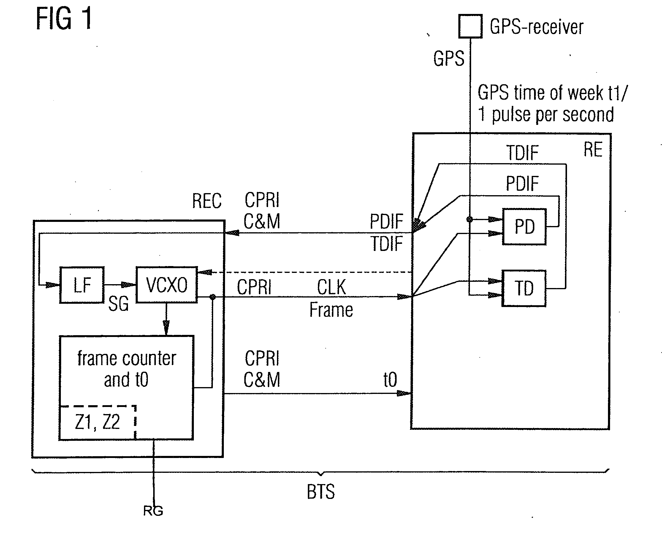
[0016]FIG. 1 shows a first exemplary embodiment of the method proposed by the inventors.

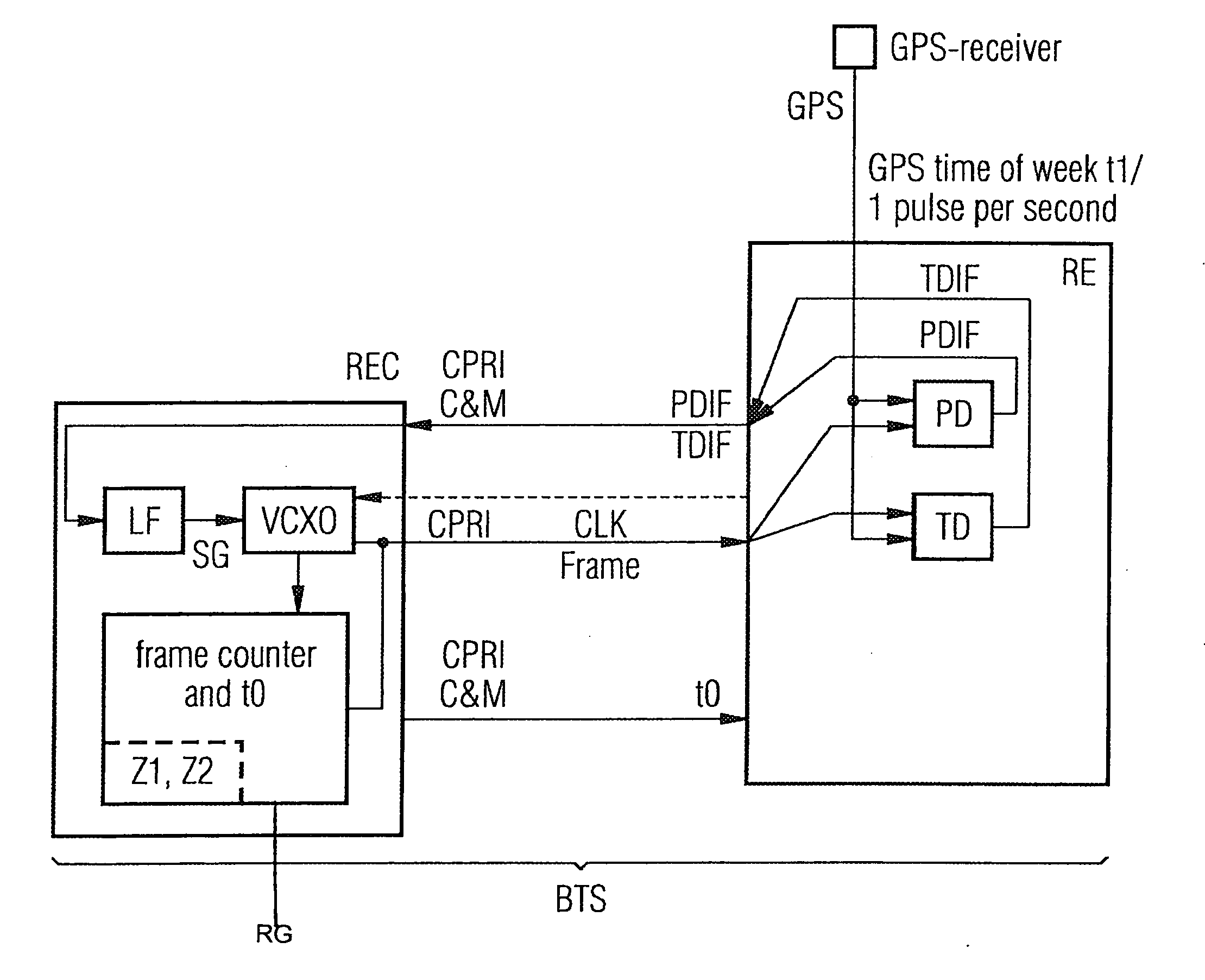
[0017]A first assembly REC and a second assembly RE in a base station BTS are preferably interconnected via a network CPRI. The CPRI network enables synchronous transmission of signals with a predictable propagation time between the assemblies RE and REC.

[0018]The first assembly REC includes an oscillator VCXO and a frame generator RG, a local clock signal CLK being formed with the aid of the oscillator VCXO, and a Frame being formed with the aid of the frame generator RG.

[0019]The local clock signal CLK and the Frame are transmitted to a second assembly RE by using synchronous transmission with a predictable propagation time.

[0020]A layer1 protocol of the CPRI network is ...


PUM


Abstract

A method synchronizes assemblies in a base station to a reference clock signal. A local clock signal and a frame are formed in a first assembly. The clock signal and the frame are transmitted, using a synchronous transmission with a predictable propagation time, to a second assembly. A reference clock signal is received in the second assembly, and a phase difference and a time difference between the transmitted clock signal on the one hand and the reference clock signal on the other hand are determined. The phase difference and the time difference are transmitted from the second assembly to the first assembly via a link without a predictable propagation time. The phase difference and the time difference are used in the first assembly to determine a manipulated variable which controls the formation of the local clock signal, such that the first and the second assemblies are synchronized in time.

Description

CROSS REFERENCE TO RELATED APPLICATIONS[0001]This application is based on and hereby claims priority to German Application No. 10 2006 019 475.6 filed on Apr. 26, 2006 and PCT Application No. PCT / EP2007 / 053127 filed on Mar. 30, 2007, the contents of which are hereby incorporated by reference.BACKGROUND OF THE INVENTION[0002]The invention relates to a method for synchronization of assemblies in a base station with a reference clock signal.[0003]It is known for a so called “master oscillator” that must have a high absolute frequency accuracy to be used to synchronize remote units or assemblies in a base station. In this case, the oscillator is tuned via a phase-locking loop to a reference signal of a generally external reference source.[0004]For example, a GPS (“Global Positioning System”) signal that is received via a GPS antenna is used as reference for an absolute time accuracy or phase accuracy. The GPS antenna is usually arranged in this case near a transceiving antenna in the ba...

Claims


Application Information

Patent Timeline
Patent Type & Authority Applications(United States)
IPC IPC(8): H04J3/06H04M1/00
CPCH04J3/0691H04B7/2693
Inventor BOMMAS, HELMUTSPLETT, ARMIN
Owner RPX CORP
Why Eureka
Try Eureka