Dynamic microphone

a microphone and dynamic technology, applied in the field of dynamic microphones, can solve the problems of hindering the design of other parts, increasing and the inability to increase the volume of the back air chamber itself, so as to reduce the acoustic impedance of the back air chamber

Inactive Publication Date: 2009-09-24
AUDIO-TECHNICA
View PDF3 Cites 7 Cited by
  • Summary
  • Abstract
  • Description
  • Claims
  • Application Information

AI Technical Summary

Benefits of technology

[0020]Among the non-directional microphone units, especially, an electret condenser microphone unit and a piezoelectric microphone unit that do not require a power source are more favorable. However, for a microphone incorporating a battery, such as a wireless microphone, or a microphone supplied with electric power through a wire, a condenser microphone unit may be used.
[0021]According to the present invention, the additional microphone unit is provided to deliver a sound signal upon receipt of sound waves arriving at the microphone unit; the membrane plate consisting of a piezoelectric element, which deforms curvedly toward the back air chamber side according to an applied voltage, is provided between the acoustic resistance material and the back air chamber; and the sound signal delivered from the additional microphone unit is applied to the membrane plate with the increase in pressure on the front surface side of the diaphragm. Therefore, the membrane plate operates so as to compress the back air chamber, and thereby the acoustic impedance of the back air chamber is decreased equivalently, so that even if the back air chamber is small, sounds with a low frequency (low range) can be captured.

Problems solved by technology

However, the increase in volume of the back air chamber 12a hinders the design of other parts.
Therefore, the volume of the back air chamber itself cannot be increased further.

Method used


Image

  • Dynamic microphone
  • Dynamic microphone
  • Dynamic microphone

Examples


Embodiment Construction

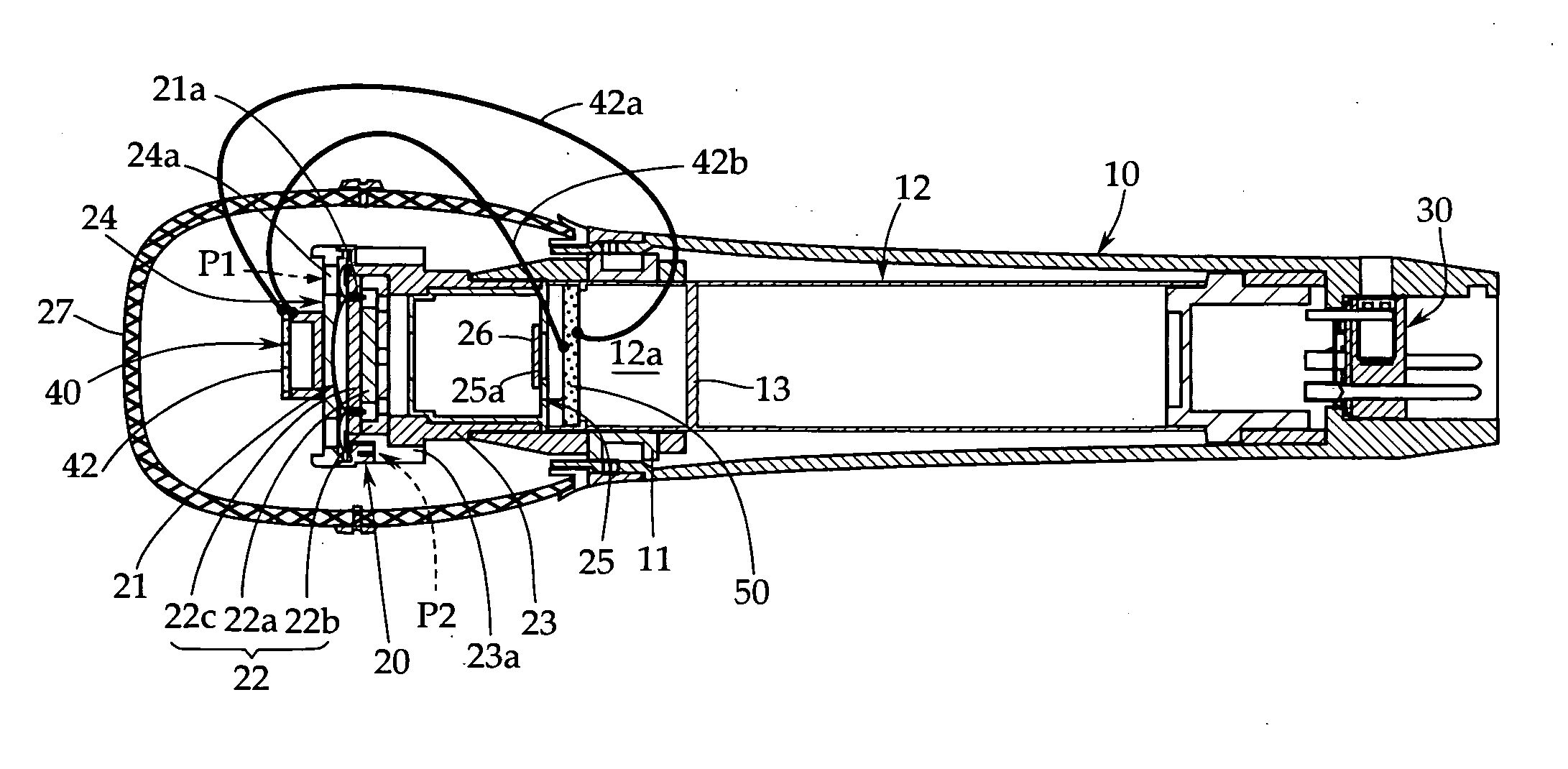
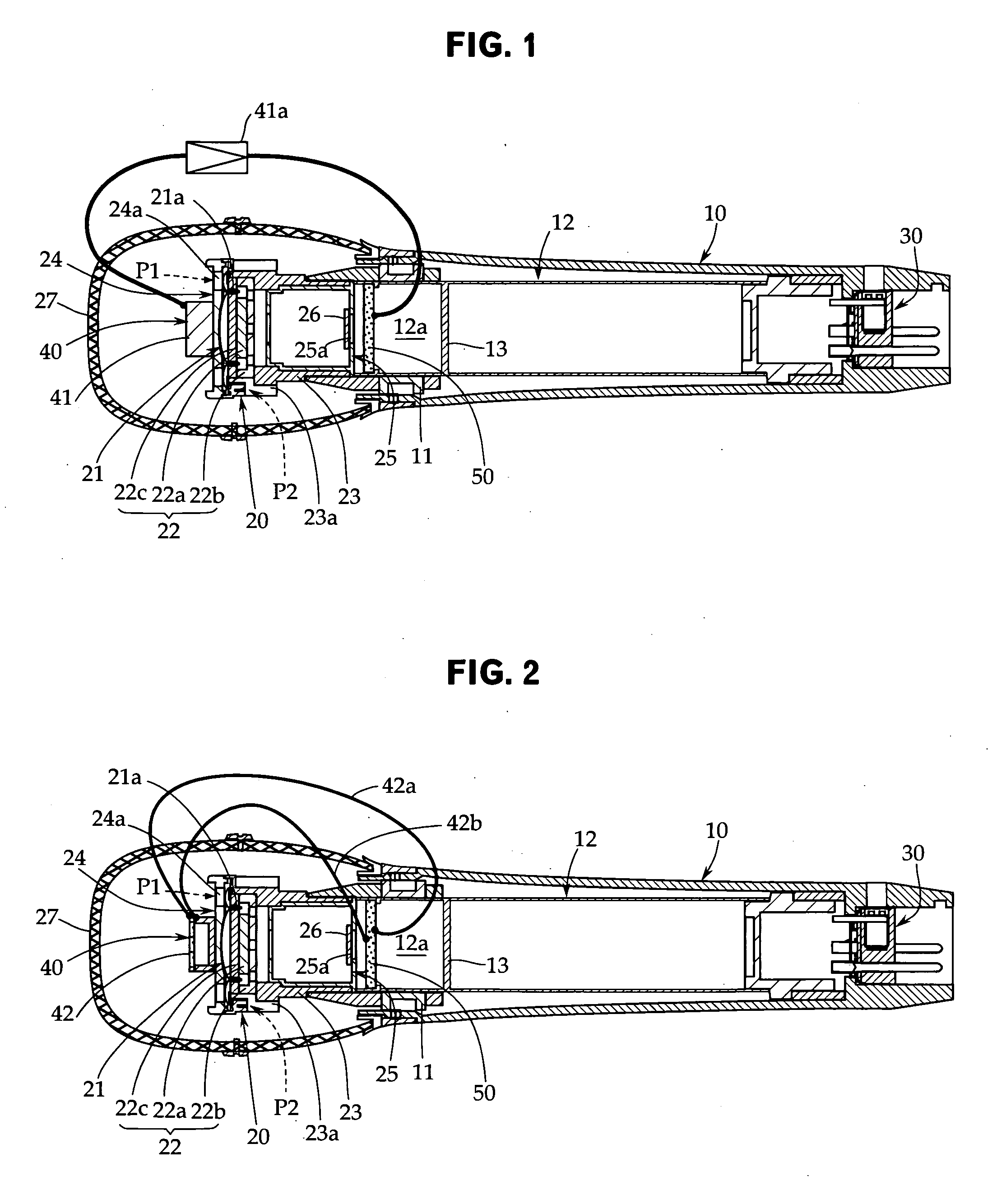
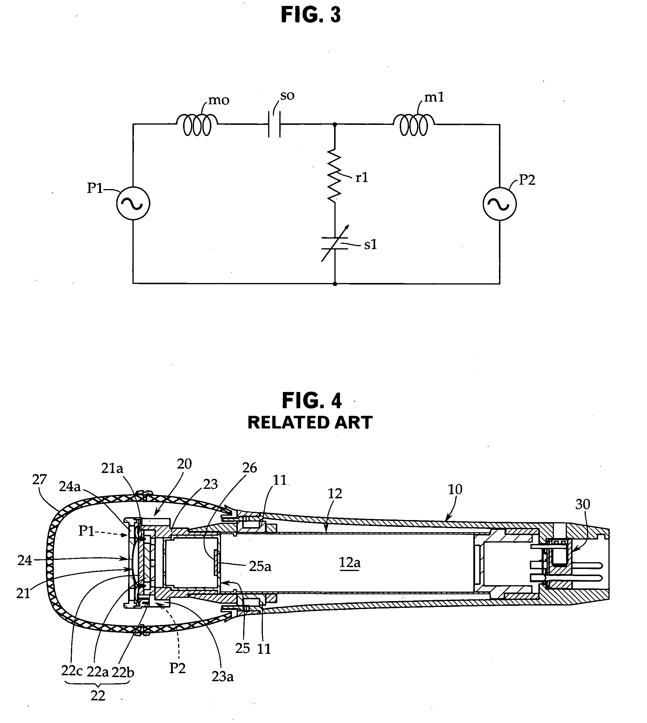
[0027]Embodiments of the present invention will now be described with reference to FIGS. 1 to 3. FIG. 1 is a sectional view of a dynamic microphone in accordance with a first embodiment of the present invention. FIG. 2 is a sectional view of a dynamic microphone in accordance with a second embodiment of the present invention. FIG. 3 is an acoustic equivalent circuit diagram for the dynamic microphones in accordance with the above-described embodiments. The same reference symbols are applied to elements that are the same as those of the conventional example explained before with reference to FIG. 4.

[0028]First, the first embodiment shown in FIG. 1 is explained. This dynamic microphone includes a cylindrical microphone case 10 made of a metal such as brass alloy, which is used as a grip part.

[0029]In this embodiment as well, in the microphone case 10, an internal cylinder 12 is held coaxially via a shock mount member 11 consisting of a rubber elastic body, and a microphone unit 20 is ...


PUM


Abstract

Even in the case where the volume of a back air chamber is small, sounds with a low frequency (low range) can be captured by equivalently decreasing the acoustic impedance of the back air chamber. A dynamic microphone includes a microphone unit 20 that includes a diaphragm 21 having a voice coil 21a and a magnetic circuit 22 having a magnetic gap; and a microphone case 10 that supports the microphone unit 20 on one end side thereof and has the back air chamber 12a provided on the back surface side of the diaphragm 21 via an acoustic resistance material 26 therein. In this dynamic microphone, an additional microphone unit 40 is provided besides the microphone unit 20; a membrane plate 50 consisting of a piezoelectric element, which deforms curvedly toward the back air chamber 12a side according to an applied voltage, is provided between the acoustic resistance material 26 and the back air chamber 12a; and the membrane plate 50 is driven by the sound signal (voltage signal) delivered from the additional microphone unit 40. Thereby, the acoustic impedance of the back air chamber 12a is decreased equivalently.

Description

CROSS-REFERENCE TO RELATED APPLICATIONS[0001]The present application is based on, and claims priority from, Japanese Application Serial Number JP2008-075319, filed Mar. 24, 2008, the disclosure of which is hereby incorporated by reference herein in its entirety.TECHNICAL FIELD[0002]The present invention relates to a dynamic microphone. More particularly, it relates to a technique in which the acoustic impedance of a back air chamber provided on the back side of a diaphragm is decreased equivalently when the pressure on the front side of the diaphragm increases, whereby sounds to a low range can be captured.BACKGROUND ART[0003]The general configuration of a dynamic microphone is explained with reference to FIG. 4. The dynamic microphone, which is mainly used for vocals and speech, includes a cylindrical microphone case 10 serving as a grip part. Usually, the microphone case 10 is made of a metal such as brass alloy.[0004]In this example, in the microphone case 10, an internal cylinde...

Claims


Application Information

Patent Timeline
Patent Type & Authority Applications(United States)
IPC IPC(8): H04R9/08
CPCH04R1/083H04R2410/00H04R1/2807
Inventor AKINO, HIROSHI
Owner AUDIO-TECHNICA
Why Eureka
Try Eureka