Electroacoustic transducer

a transducer and electroacoustic technology, applied in the direction of transducer details, electrical transducers, electrical apparatus, etc., can solve the problems of poor directional frequency response and sound quality in bass sound, diaphragms are then difficult to vibrate, and the air chamber cannot be large enough to provide a large air chamber like a wired microphone, so as to reduce the acoustic impedance and enhance the directional frequency response

Inactive Publication Date: 2012-02-02
AUDIO-TECHNICA
View PDF3 Cites 12 Cited by
  • Summary
  • Abstract
  • Description
  • Claims
  • Application Information

AI Technical Summary

Benefits of technology

[0011]As the diaphragm in the electroacoustic transducer unit vibrates, the volume of the air chamber changes and the sound pressure in the air chamber changes. The feedback control is then performed in which the sound pressure detector detects the sound pressure change and the detection signals drive the volume adjuster to eliminate the sound pressure change. This control reduces the acoustic impedance of the air chamber in an equivalent manner, thus enhancing directional frequency response particularly in bass sound. Even if an air chamber or an enclosure has a small volume in a speaker or headphones as the electroacoustic transducer, sound can be played at a sufficient sound pressure level to bass sound. Even if an air chamber is limited in size due to a power battery loaded in a microphone casing of a microphone, such as a wireless microphone, as the electroacoustic transducer, audio signals can be converted at a predetermined signal level to bass sound.

Problems solved by technology

In a hand-held wireless microphone, a transmitter circuit and a power battery should be housed in a grip, and thus a large air chamber cannot be provided like a wired microphone.
This results in poor directional frequency response and sound quality in bass sound.
The diaphragm is then difficult to vibrate, thus increasing the lowest responding frequency level and reducing the bass output level.
Thus, the membrane cannot be driven properly in accordance with the pressure change in the back air chamber.

Method used


Image

  • Electroacoustic transducer
  • Electroacoustic transducer
  • Electroacoustic transducer

Examples


first embodiment

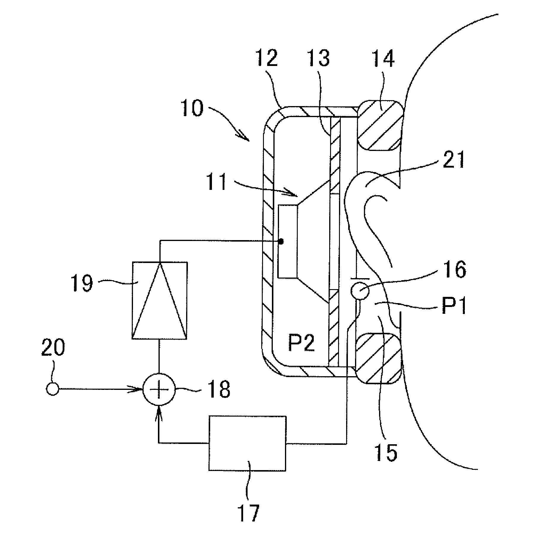
[0021]An embodiment shown in FIG. 1 is explained, in which the technological concept of the present invention is applied to headphones. In FIG. 1, each headphone 10 has a cup-shaped housing 12; a baffle plate 13 fixed to the internal periphery of the housing 12 proximate to an open end; a speaker unit 11 serving as a driver unit attached to the baffle plate 13 and surrounded by the housing 12; and an ear pad 14 mounted on the open end of the housing 12. The ear pad 14 of the headphone 10 covers an ear 21 of a user and is pressed against the side of the user's head, as commonly known. FIG. 1 illustrates a state where the headphone 10 is worn on one of the ears of the user. Headphones generally include right and left headphones to be worn on right and left ears. The right and left headphones are connected by a headband or a neckband. FIG. 1 illustrates an example ear-covering type headphone having the ear pad 14 covering an ear 21. An ear-mounted type may be employed, in which the ear...

second embodiment

[0037]An embodiment shown in FIG. 7 is explained, in which the technological concept of the present invention is applied to a speaker system. An electroacoustic transducer in the embodiment shown in FIG. 7 is an example speaker system in which a speaker unit 41 is built into an enclosure 40. The inside of the enclosure 40 is partitioned by a partitioning plate 46. The front plate of the enclosure 40 is a baffle plate 44. An air chamber 43 is defined between the baffle plate 44 and the partitioning plate 46. The speaker unit 41 as an electroacoustic transducer unit is attached to the baffle plate 44 and is located inside the air chamber 43. The air chamber 43 is located in back of a diaphragm 42 of the speaker unit 41. A volume adjuster 47 is attached to the partitioning plate 46. Similar to the speaker unit 41, the volume adjuster 47 has a structure similar to that of a dynamic speaker unit. The volume adjuster 47 has a diaphragm 48, whose front surface faces the air chamber 43. A m...

third embodiment

[0041]FIG. 8 illustrates an embodiment of the technological concept of the present invention that is applied to a dynamic microphone. In FIG. 8, the dynamic microphone 50 has a microphone casing 51 that also serves as a grip. A dynamic microphone unit 52, which is an electroacoustic transducer unit, is appropriately mounted in the front end of the microphone casing 51. The microphone unit 52 has a unit casing 54. A diaphragm 53 that vibrates in response to sound waves is disposed inside the internal periphery in the front end of the unit casing 54. The diaphragm 53 has a voice coil, which is disposed in a magnetic gap formed by magnetic circuit members, such as a permanent magnet and a yoke. The diaphragm 53 vibrates in response to sound waves along with the voice coil, which then outputs audio signals corresponding to the sound waves due to electromagnetic conversion.

[0042]The unit casing 54 is provided with an air chamber 56 in back of the diaphragm 53 and the magnetic circuit mem...


PUM


Abstract

An electroacoustic transducer includes a diaphragm, an electroacoustic transducer unit having the diaphragm, and an air chamber having the diaphragm of the electroacoustic transducer unit and having a variable volume in response to vibration of the diaphragm. The air chamber has a sound pressure detector detecting a sound pressure in the air chamber and a volume adjuster driven by the output signals from the sound pressure detector, changing the volume of the air chamber in response to the output signals, and controlling the acoustic impedance of the air chamber. A control system from the sound pressure detector to the volume adjuster configures a feedback control system increasing the volume of the air chamber with an increase in the sound pressure in the air chamber.

Description

BACKGROUND OF THE INVENTION[0001]1. Field of the Invention[0002]The present invention relates to an electroacoustic transducer having an air chamber in back of a diaphragm, the electroacoustic transducer actively canceling a sound pressure generated in the air chamber such that the air chamber functions as a large-volume air chamber even if the air chamber has a small volume, and thus enhancing bass response.[0003]2. Related Background Art[0004]Electroacoustic transducers, for example, unidirectional dynamic microphones, omnidirectional dynamic microphones, headphones, and speakers may each have an air chamber to prevent sound waves from entering from the outside. Such an electroacoustic transducer has a diaphragm that vibrates in response to sound waves or generates sound waves as being driven by audio signals. The air chamber is provided in back of the diaphragm. The air chamber functions as an acoustic capacitance. Specifically, a large air chamber functions as a lowly resilient ...

Claims


Application Information

Patent Timeline
Patent Type & Authority Applications(United States)
IPC IPC(8): H04R1/20
CPCH04R3/04H04R1/28
Inventor AKINO, HIROSHI
Owner AUDIO-TECHNICA
Why Eureka
Try Eureka