High power optical connector and optical fiber system using the same

a technology of optical connectors and optical fibers, applied in the field of high-power optical connectors, can solve the problems of changing the characteristics of the ferrule, storing heat, and reducing the service life of the connector, so as to prevent heat accumulation, shorten the service life, and detect quickly

Active Publication Date: 2009-09-24
THE FUJIKURA CABLE WORKS LTD
View PDF4 Cites 12 Cited by
  • Summary
  • Abstract
  • Description
  • Claims
  • Application Information

AI Technical Summary

Benefits of technology

[0029]In the high power optical connector described in (1), the ferrule of the receiving-side optical connector is made of the transparent glass and the flange is made of the transparent material which transmits infrared light, so that light leakage can be allowed to transmit through the glass ferrule and the transparent flange to exit outside. As a result, it prevents heat from accumulating in the high power optical connector. Therefore, the high power optical connector is not damaged when used for connection of optical fibers for high power light transmission and guarantees a long life-span.
[0030]In addition, in the case of (2), light leakage can be detected by the sensor. As a result, as compared with the case where light leakage is detected by the temperature sensor, light leakage can be detected in a shorter time after a connection loss occurs.
[0031]In addition, in the case of (3) or (4), light leakage can be scattered by the flange. As a result, the light leakage can be scattered to enter the sensor. Therefore, a connection error in the plurality of the optical connectors can be rapidly detected by using the single sensor.
[0032]In addition, in the case of (6), light leakage does not reflect in the ferrule and spreads out. Therefore, components around the ferrule do not absorb the light leakage, and thus it is less likely that the heat generation is worried.
[0033]In addition, in the case of (5), the same effects as those of the high power optical connector described in (1) can be obtained.
[0034]In addition, in the optical fiber system of (7), the same effects as those of the high power optical connector described in (1) can be obtained.

Problems solved by technology

As a result, there is a concern that changes in characteristics such as degradation of adhesion and an increase in absorptance occur.
Accordingly, light leakage is absorbed by the zirconia ferrule which results in storing heat.
As a result, when high power light leaks, the temperature of the ferrule portion rapidly increases, and the adhesive and the like may be damaged.
In this structure, when the temperature increase is detected, there is a high possibility in that the end face is already damaged.
Therefore, reliability is low.
This results in low reliability.
However, in the case of a high power light transmission of about 10 W which is the target of the present invention, temperature increase in a position irradiated by light leakage is high even though a mode field diameter is increased, and this may damage the structure.
However, in this structure, a connection loss is greater than that of a PC (physical contact) connection.
This results in increases in power consumption and costs.

Method used


Image

  • High power optical connector and optical fiber system using the same
  • High power optical connector and optical fiber system using the same
  • High power optical connector and optical fiber system using the same

Examples


first embodiment

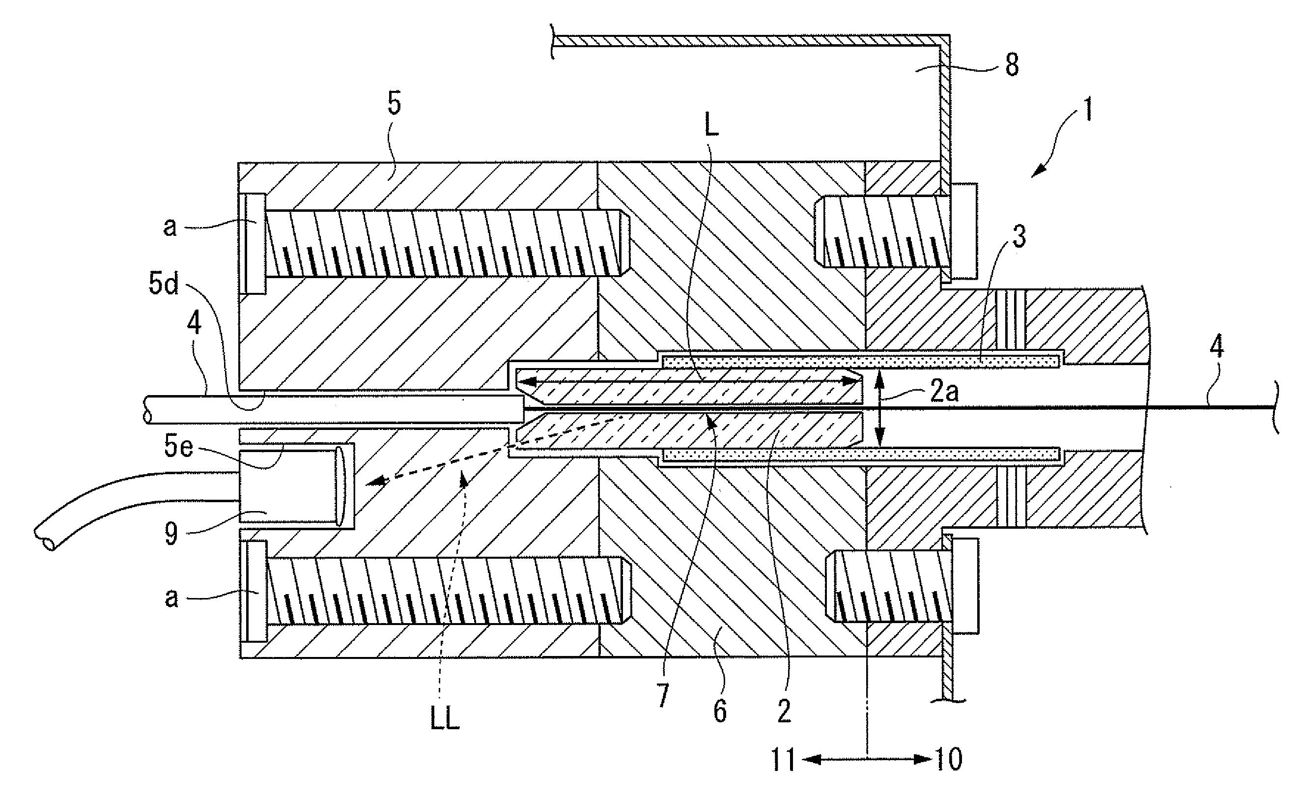
[0041]FIG. 1 is a cross-sectional view illustrating a main portion from a cross-sectional view including an axis of an optical fiber, according to a first embodiment of the high power optical connector of the present invention. In FIG. 1, reference numeral 1 denotes the high power optical connector (hereinafter, referred to as optical connector), reference numeral 2 denotes a glass ferrule, reference numeral 3 denotes a zirconia sleeve, reference numeral 4 denotes an optical fiber, reference numeral 5 denotes a flange, reference numeral 6 denotes a housing, reference numeral 7 denotes an adhesive, reference numeral 8 denotes a chassis, reference numeral 9 denotes a photodiode (hereinafter, abbreviated to PD) used as a sensor, reference numeral 10 denotes an excitation light source side (hereinafter, denoted by LD side), and reference numeral 11 denotes a receiving side.

[0042]In FIG. 1, only the glass ferrule 2 of the optical connector 1 on the receiving side 11 is shown, and a ferru...

second embodiment

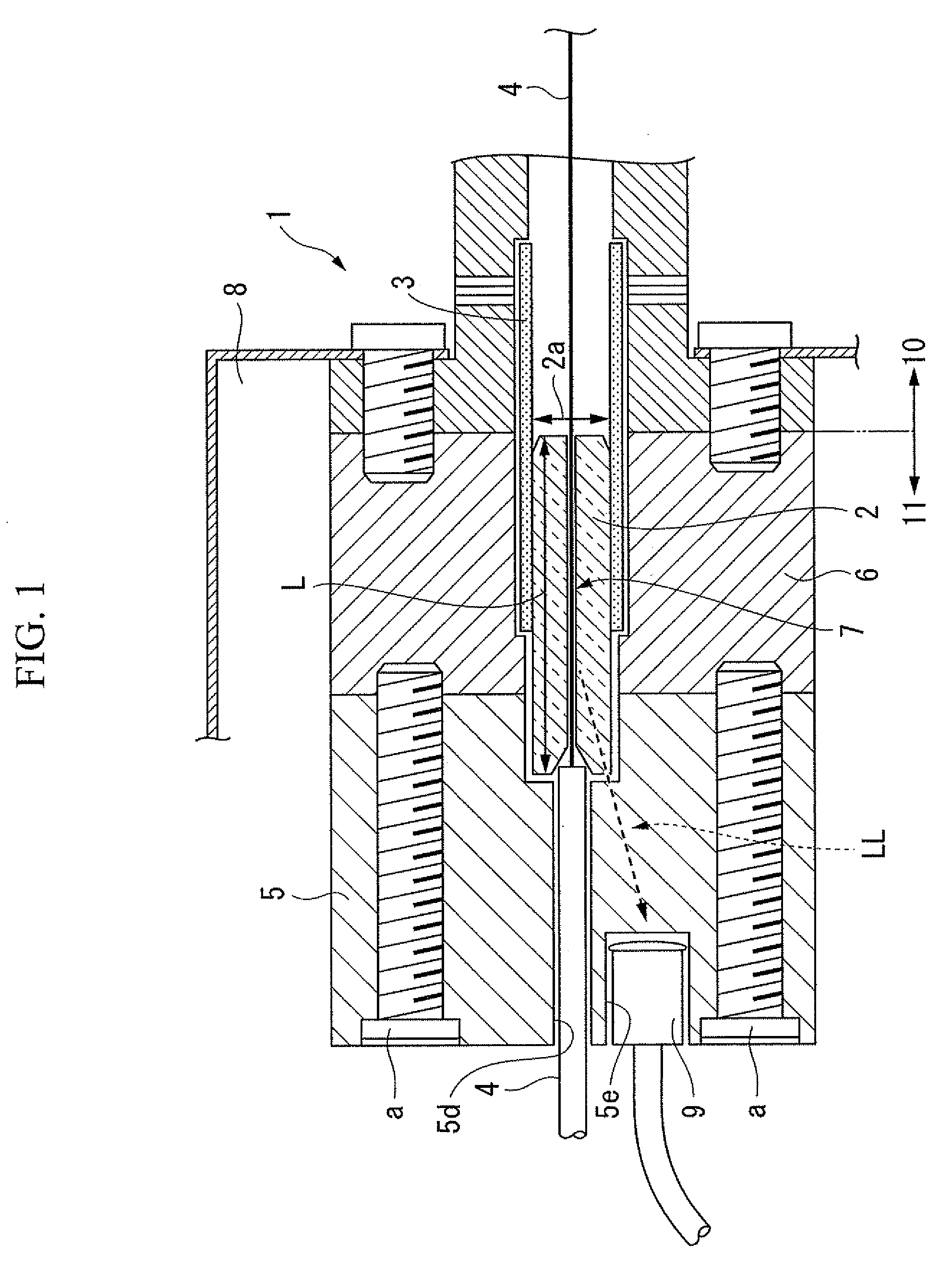
[0057]FIG. 2 is a cross-sectional view illustrating a main portion from a cross-sectional view including an axis of an optical fiber, according to a second embodiment of the high power optical connector of the present invention. In the following description, like elements corresponding to the elements of the first embodiment are denoted by like reference numerals, and only differences between the embodiments are described.

[0058]In this embodiment, a plurality of glass ferrules 2 is mounted to a flange 5. In addition, the flange 5 is added with fine particles (for example silica), and by the fine particles, infrared light transmitting through the flange 5 is scattered.

[0059]In addition, in the example of FIG. 2, at the peripheral surface of the flange 5, a reflective layer 13 for allowing light that propagates to leak out of the peripheral surface to be reflected toward the PD 9, is provided. The reflective layer 13 can be omitted.

[0060]In the configuration of the embodiment, the plu...

third embodiment

[0062]FIG. 3A is a cross-sectional view illustrating a main portion from a cross-sectional view including an axis of an optical fiber, according to a third embodiment of the high power optical connector of the present invention. In the following description, like elements corresponding to the elements of the second embodiment are denoted by like reference numerals, and only differences between the embodiments are described.

[0063]In this embodiment, similarly to the second embodiment, a configuration in which a plurality of glass ferrules 2 is mounted to the flange 5, and at a surface 5b on the opposite side to a connection-side surface 5a of the flange 5, a scattering layer 14 for scattering light leakage LL which exits from the surface 5b is provided, is employed. In addition, a PD 9 is disposed to face the rear of the scattering layer 14.

[0064]In this embodiment, as the flange 5, similarly to the second embodiment, a flange 5 added with fine particles may be used, or a flange 5 th...


PUM


Abstract

This high power optical connector is used at least on a light-receiving side of an optical fiber. The high power optical connector is provided with: a housing; a ferrule which is accommodated in the housing to retain the optical fiber; and a flange which is connected and fixed to the housing while being in contact with an end portion of the ferrule. The ferrule is made of a transparent glass; and the flange is made of a transparent material which transmits a light which propagates through the optical fiber.

Description

[0001]Priority is claimed on Japanese Patent Application No. 2008-069292, filed on Mar. 18, 2008, the contents of which are incorporated herein by reference.BACKGROUND OF THE INVENTION[0002]1. Field of the Invention[0003]The present invention relates to a high power optical connector, and more particularly, to a high power optical connector suitable for connection of an optical fiber for high power transmission of several hundreds of mW to several tens of W. In addition, the present invention relates to an optical fiber system using the high power optical connector on a receiving side.[0004]2. Description of the Related Art[0005]Conventional arts in relation to the present invention are disclosed in, for examples, Patent Documents described as follows.[0006]In Japanese Unexamined Patent Application, First Publication No. 2004-29450 (hereinafter, referred to as Patent Document 1) and Japanese Patent, Publication No. 3831315 (hereinafter, referred to as Patent Document 2), techniques ...

Claims


Application Information

Patent Timeline
Patent Type & Authority Applications(United States)
IPC IPC(8): G02B6/36
CPCG02B6/3885G02B6/3813
Inventor OBA, YASUHIRO
Owner THE FUJIKURA CABLE WORKS LTD
Why Eureka
Try Eureka