Merging video with time-decimated high-resolution imagery to form high-resolution video frames

a technology of high-resolution still images and video frames, which is applied in the direction of optical-mechanical scanning signal generators, instruments, television systems, etc., can solve the problems of high-cost solutions that are not suitable for all applications, and the introduction of artifacts can be as annoying to viewers, and achieve high-resolution video output

Active Publication Date: 2009-09-24
SONY CORP +1
View PDF3 Cites 38 Cited by
  • Summary
  • Abstract
  • Description
  • Claims
  • Application Information

AI Technical Summary

Benefits of technology

[0012]A high spatial resolution video image output is generated in response to registering a low spatial resolution (LR) video image source and intermittent still images having a high spatial resolution (HR) which are processed and blended to create a video image stream having a spatial resolution exceeding the LR video image source. The high resolution output approximates that which would arise if the intermittent HR images were coincident in time with the frames being output by the method. According to this method a high resolution video output can be generated without the need of a video imager which provides both high spatial and temporal dimensions.
[0039]Another aspect of the invention is a blending process, controlled by at least one motion estimation error measurement, which in response to receiving still image and SR image inputs generates a resultant high spatial resolution output.
[0042]Another aspect of the invention is a blending process which incorporates measuring of motion estimation error (e.g., sum of absolute differences (SAD)) between image frames in the low resolution video toward minimization of target image error.

Problems solved by technology

It will be recognized that although this produces a desirable video output stream with a minimum of artifacts, it represents a high-cost solution which is not suitable for all applications.
These techniques have shown some promise, yet suffer from a number of shortcomings.
In some cases, the artifacts introduced can be as annoying to a viewer as watching the original low-resolution video.

Method used


Image

  • Merging video with time-decimated high-resolution imagery to form high-resolution video frames
  • Merging video with time-decimated high-resolution imagery to form high-resolution video frames
  • Merging video with time-decimated high-resolution imagery to form high-resolution video frames

Examples


embodiment 10

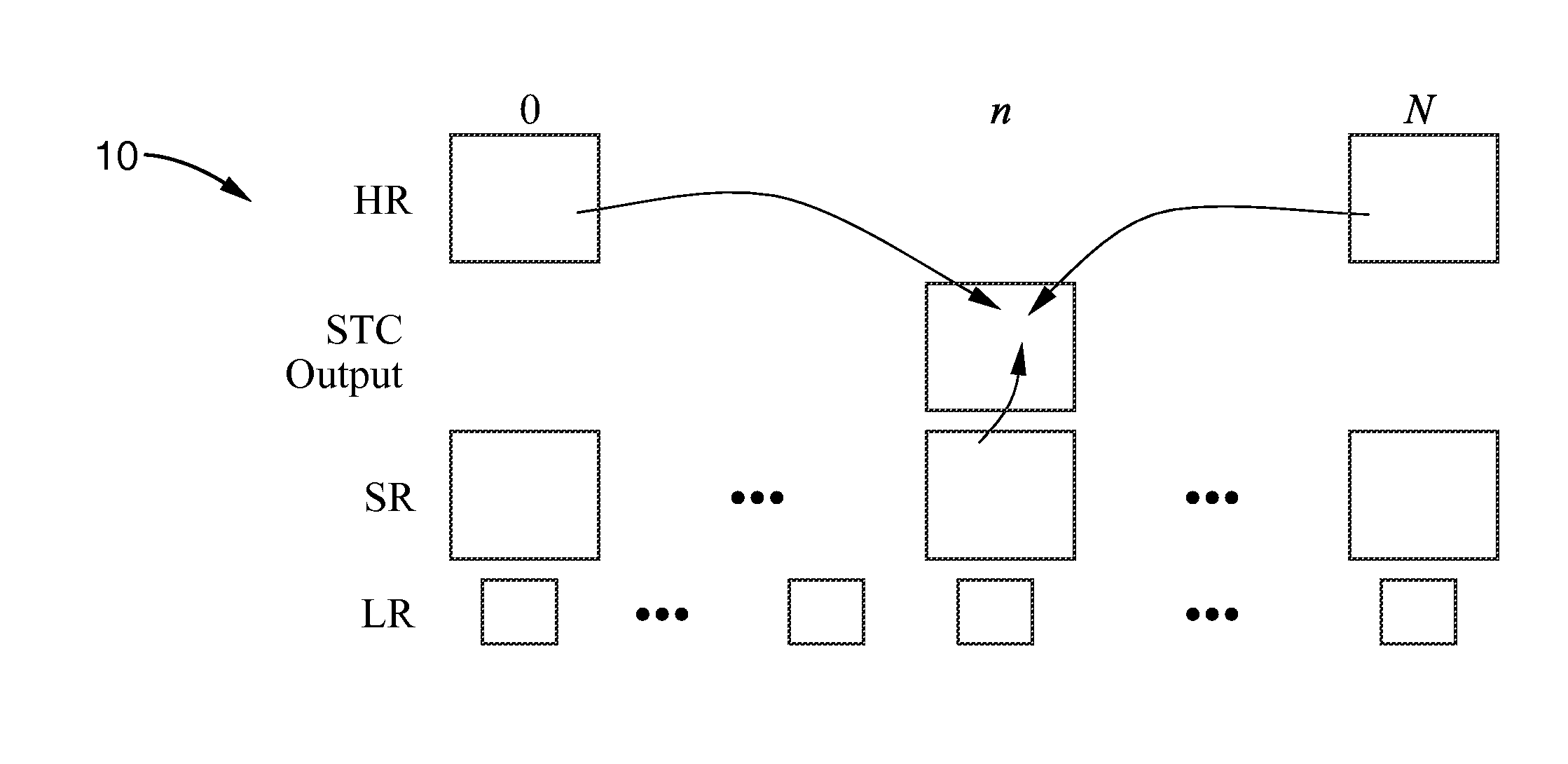
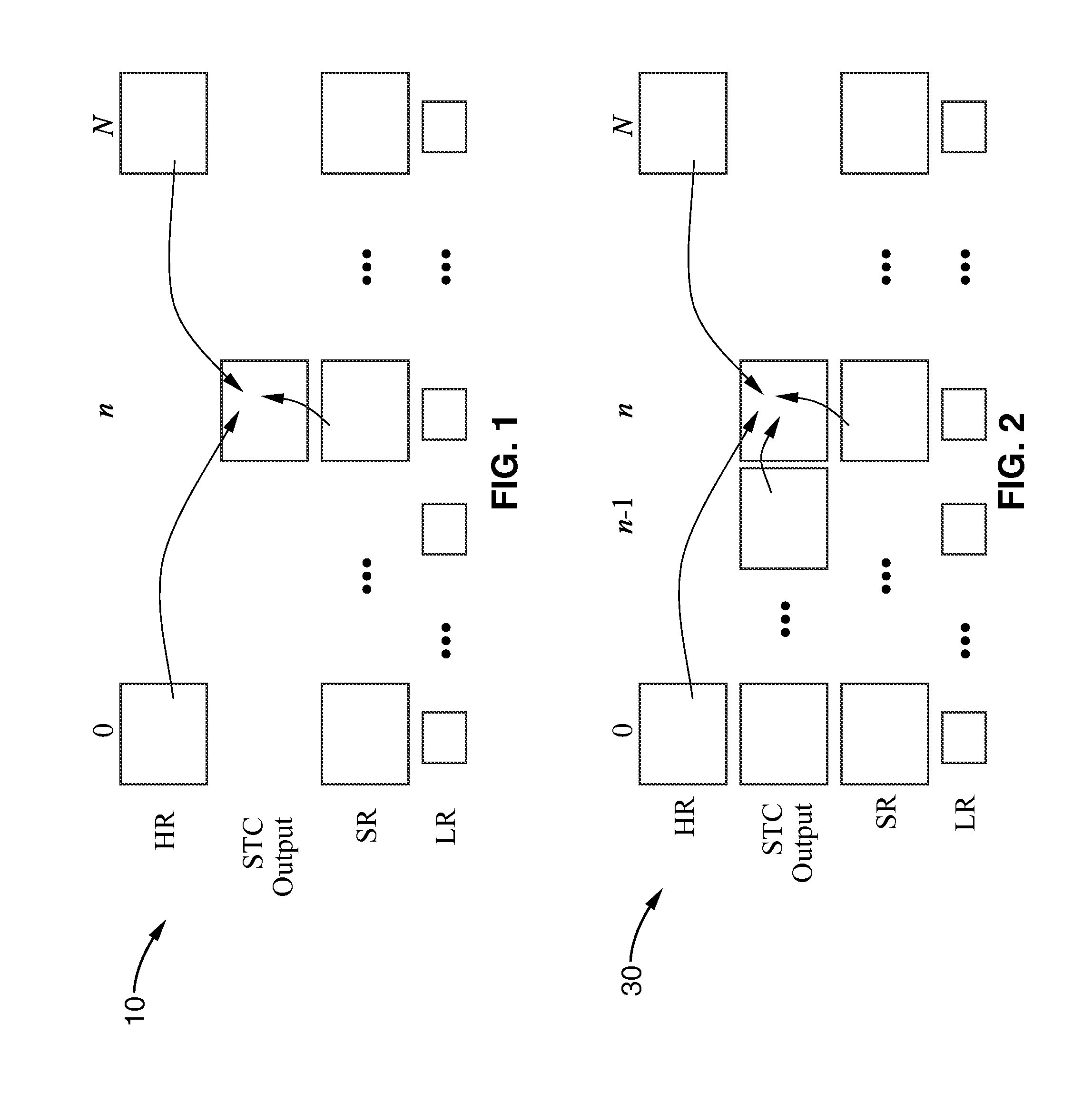
[0079]FIG. 1 illustrates an embodiment 10 of the blending method according to the invention, showing creation of a single high-resolution image temporally displaced between two still images. To determine the STC output at the desired time n, the method combines multiple pictures, this example illustrating the use of up to three pictures: (1) a high-resolution still to the left (prior time / frame) (HR0), (2) a high-resolution still to the right (later time / frame)(HRN), and (3) the super-resolved image for the desired time (current frame being assembled)(SRn). The method also utilizes the original low-resolution (LR) video frames for determining SAD values. Alternatively, the method can be configured to combine either the high-resolution still to the left (HR0)or right (HRN) with (SRn). It should be noted that input (SRn) can be any desired “higher-resolution” (“SR input”), and need not necessarily be generated by a multi-frame super-resolution algorithm.

embodiment 30

[0080]FIG. 2 illustrates an embodiment 30 which extends the STC picture blending method to each frame of the sequence. The primary difference with FIG. 1 is that the method is configured to make use of the previous STC output at time n−1, when determining the STC output for time n.

[0081]The inventive method is sufficiently generic that not all four of the example inputs need to be utilized. For example, some applications may only have a single HR input, and only require a single STC output at a particular time. In such a case, the method can be readily configured to combine just HR0 and SRn when forming the STC output.

[0082]The following discussion centers on the procedure for the case of FIG. 2, in relation to which the case of FIG. 1 can be generally considered a simplified subset of that which is taught for FIG. 2.

embodiment 50

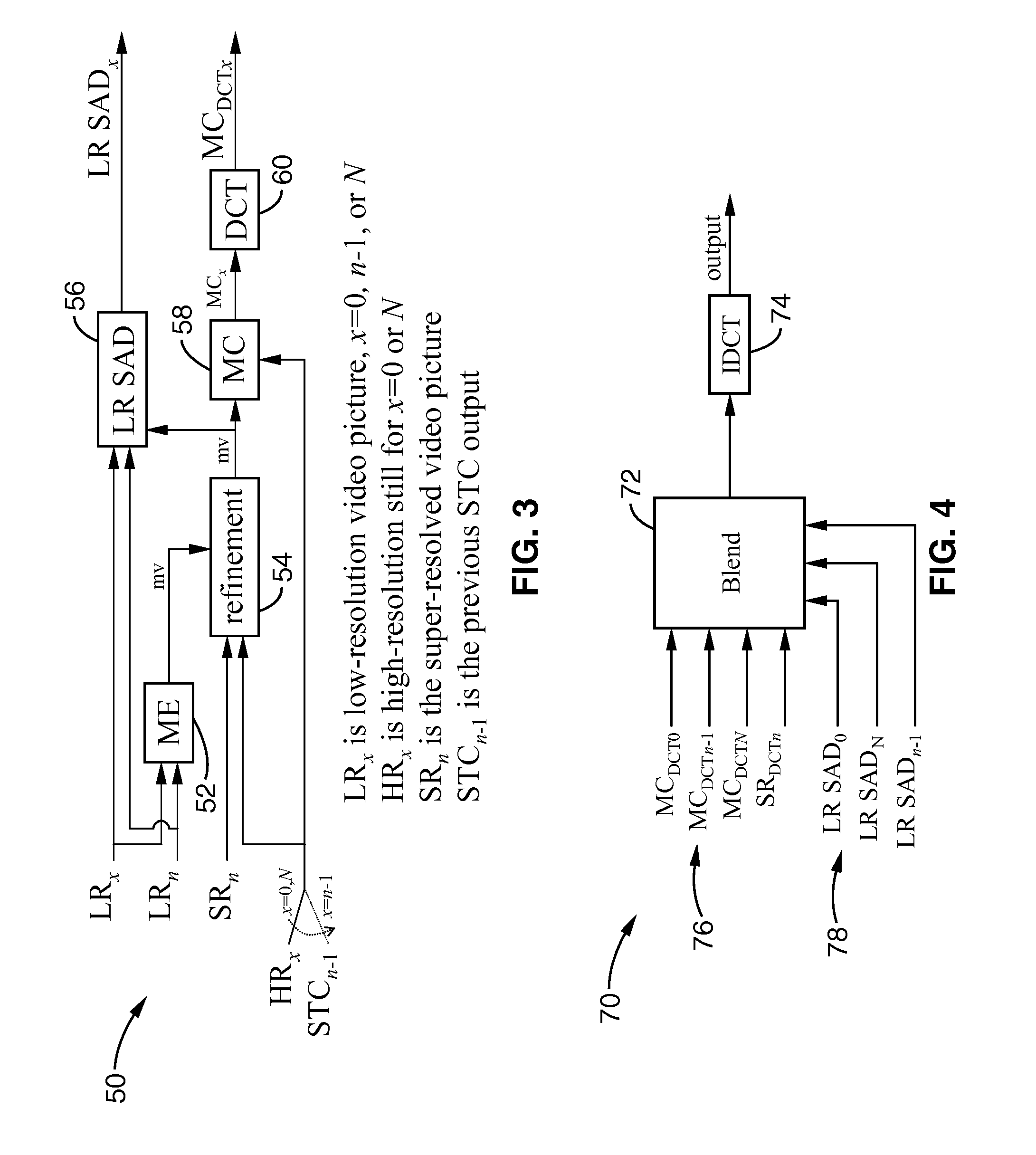
[0083]FIG. 3 illustrates an embodiment 50 of a procedure that can be applied to the high-resolution inputs toward generating an enhanced spatial resolution shutter-time compensated video output. It should be appreciated that the procedural elements can be embodied as a method, or within an apparatus such as programming executable on a computer configured for processing video images, or as a computer readable media containing programming executable on a computer configured for processing video images, or as combinations and variations thereof.

[0084]The high resolution inputs shown in FIG. 3 do not represent the desired image frame (shutter-time compensated frame), thus they can be said to be shutter times that are temporally displaced from that of the high resolution video image to be output. In the present case, these three high-resolution inputs are HR0, HRN, and STCn−1. First, the method performs motion estimation (ME) 52 on the low-resolution (LR) frames. Then the LR motion resul...


PUM


Abstract

Apparatus and methods for generating a shutter-time compensated high spatial resolution (HR) image output by enhancing lower spatial resolution (LR) video images with information obtained from higher spatial resolution still images which are temporally decimated. Super-resolved images and LR SAD information is generated from the LR images and used for directing the extracting of information from the temporally decimated HR images to enhance the spatial resolution of the LR images in a blending process. By way of example blending can comprise: motion estimation, motion compensation of a temporally displaced HR still images and a super-resolved (SR) image input, transformation (e.g., DCT), generating motion error output, blending motion compensated images in response to LR motion error information; inverse-transformation into a shutter-time compensated HR video image output. Accordingly, a more cost effective solution is taught for obtaining a desired shutter time and video resolution.

Description

CROSS-REFERENCE TO RELATED APPLICATIONS[0001]Not ApplicableSTATEMENT REGARDING FEDERALLY SPONSORED RESEARCH OR DEVELOPMENT[0002]Not ApplicableINCORPORATION-BY-REFERENCE OF MATERIAL SUBMITTED ON A COMPACT DISC[0003]Not ApplicableNOTICE OF MATERIAL SUBJECT TO COPYRIGHT PROTECTION[0004]A portion of the material in this patent document is subject to copyright protection under the copyright laws of the United States and of other countries. The owner of the copyright rights has no objection to the facsimile reproduction by anyone of the patent document or the patent disclosure, as it appears in the United States Patent and Trademark Office publicly available file or records, but otherwise reserves all copyright rights whatsoever. The copyright owner does not hereby waive any of its rights to have this patent document maintained in secrecy, including without limitation its rights pursuant to 37 C.F.R. §1.14.BACKGROUND OF THE INVENTION[0005]1. Field of the Invention[0006]This invention pert...

Claims


Application Information

Patent Timeline
Patent Type & Authority Applications(United States)
IPC IPC(8): H04N11/24
CPCG06T3/4053
Inventor ROBERTSON, MARKLIU, MING-CHANG
Owner SONY CORP
Why Eureka
Try Eureka