Friction-Joining Steel Plate and Friction-Joining Structure

Inactive Publication Date: 2009-09-24
NIPPON STEEL & SUMIKIN ENG CO LTD +1
View PDF0 Cites 2 Cited by
  • Summary
  • Abstract
  • Description
  • Claims
  • Application Information

AI Technical Summary

Benefits of technology

[0010]According to the above-described present invention, since the portion of projected streaks on the friction-joining steel plate is set to be harder than the surface of the steel products to be joined (preferably, at least three times higher in hardness), the projected streaks on the friction-joining steel plate can enter more easily into the steel products to be joined, and a frictional resistance resulting from mechanical slip resistance of the thus entered friction-joining steel plate acts between the steel products to be joined, thereby, making it possible to increase remarkably a friction coefficient between the steel products to be joined via the friction-joining steel plate. As a result, a friction-joining structure is constituted by a slip resistance mechanism which can be easily validated from a theoretical or an experimental point of view and is also small in variance of friction coefficient. It is, therefore, possible to set a friction coefficient in design to be a high value with accuracy and also realize a rational design. In other words, the friction coefficient can be set higher than in a conventional case to reduce the number of bolts or miniaturize the diameter thereof, thus making it possible to keep the partial loss of area of a base material to a minimum extent. Further, by making a splice plate and a gusset plate smaller, it is possible to reduce the quantity of steel products and also reduce material / construction costs necessary for architectural structures and civil engineering construction.
[0043]The above-described friction-joining steel plate and the friction-joining structure of the present invention are applicable to various friction joining portions at low cost and also able to reliably increase frictional resistance, thereby realizing a rational design.

Problems solved by technology

However, these methods only generate a relatively small friction coefficient on the friction surface and also have difficulty in securing a stable frictional resistance.
Thereby, there is no choice but to adopt a lower value, with consideration given to safety in design, making it difficult to provide a rational design.
However, in a conventional friction-joining structure described in the above-described Patent Document 1, since joining faces of steel products to be joined are subjected to one-time or multiple-time shot blasting to form a friction surface, it is necessary to process many steel products to be joined which are available in a wide variety, thus resulting in an increase in labor and time and raising the processing cost, which poses a problem.
Further, even if a method including shot blasting is used to make different the hardness and the roughness of a friction surface to raise friction coefficients of the friction surface, there still remains a wide variance in the thus obtained friction coefficients.
Consequently, there is not a substantial improvement in the upper limit of the friction-coefficients available in design as expected, thus, resulting in a smaller cost-effectiveness, which poses another problem.

Method used


Image

  • Friction-Joining Steel Plate and Friction-Joining Structure
  • Friction-Joining Steel Plate and Friction-Joining Structure
  • Friction-Joining Steel Plate and Friction-Joining Structure

Examples


examples

[0100]Hereinafter, a description will be made of an example experimentally verified for the friction-joining structure of the embodiment.

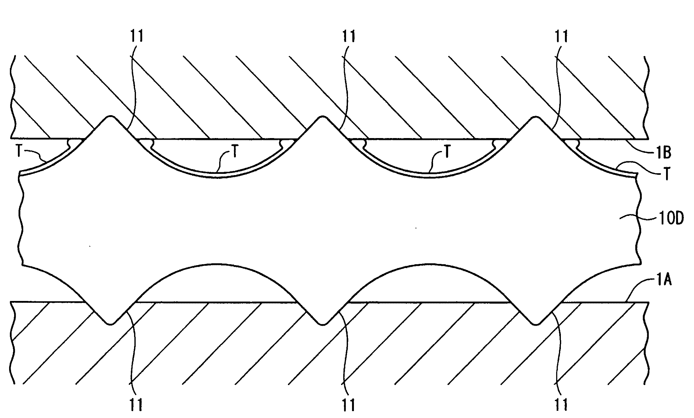
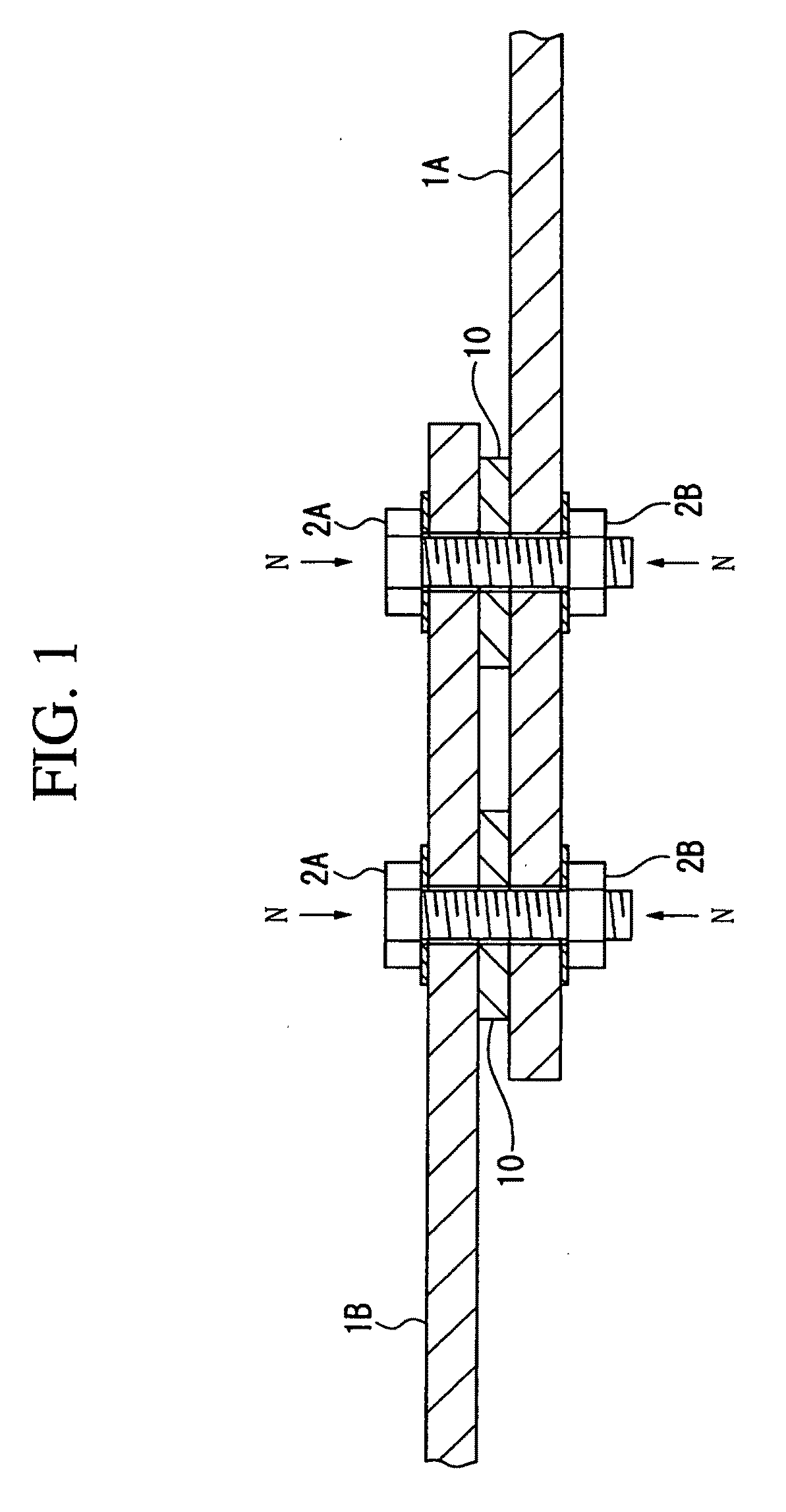
[0101]In the following embodiment, a tensile strength test is conducted in which the friction-joining steel plate 10 and the steel plates 1A and 1B are fastened by using high strength bolts 2A and nuts 2B as illustrated in FIG. 1.

[0102]In this instance, the Vickers hardness ratio (rh) is given as a first parameter, the tip angle (θ) of the projected streaks 11 is given as a second parameter, and the stress intensity ratio (σ / σmb) is given as a third parameter. Then, the tensile strength test is conducted by allowing the three parameters to change, and the thus obtained friction coefficient (slip coefficient) μF is measured

(First Parameter: Vickers Hardness Ratio rh)

[0103]The Vickers hardness ratio rh is a ratio (rh=Hvh / Hvm) of the Vickers hardness (Hvh) at a portion of the projected streaks 11 on the friction-joining steel plate 10 to the Vickers h...

embodiment 1

[0126]FIG. 14 is a photo showing a friction-joining steel plate of Embodiment 1. FIG. 15 is a sectional view illustrating the friction-joining steel plate 10a of Embodiment 1. FIG. 16 is a graph illustrating the test results obtained by using the friction-joining steel plate 10a of Embodiment 1.

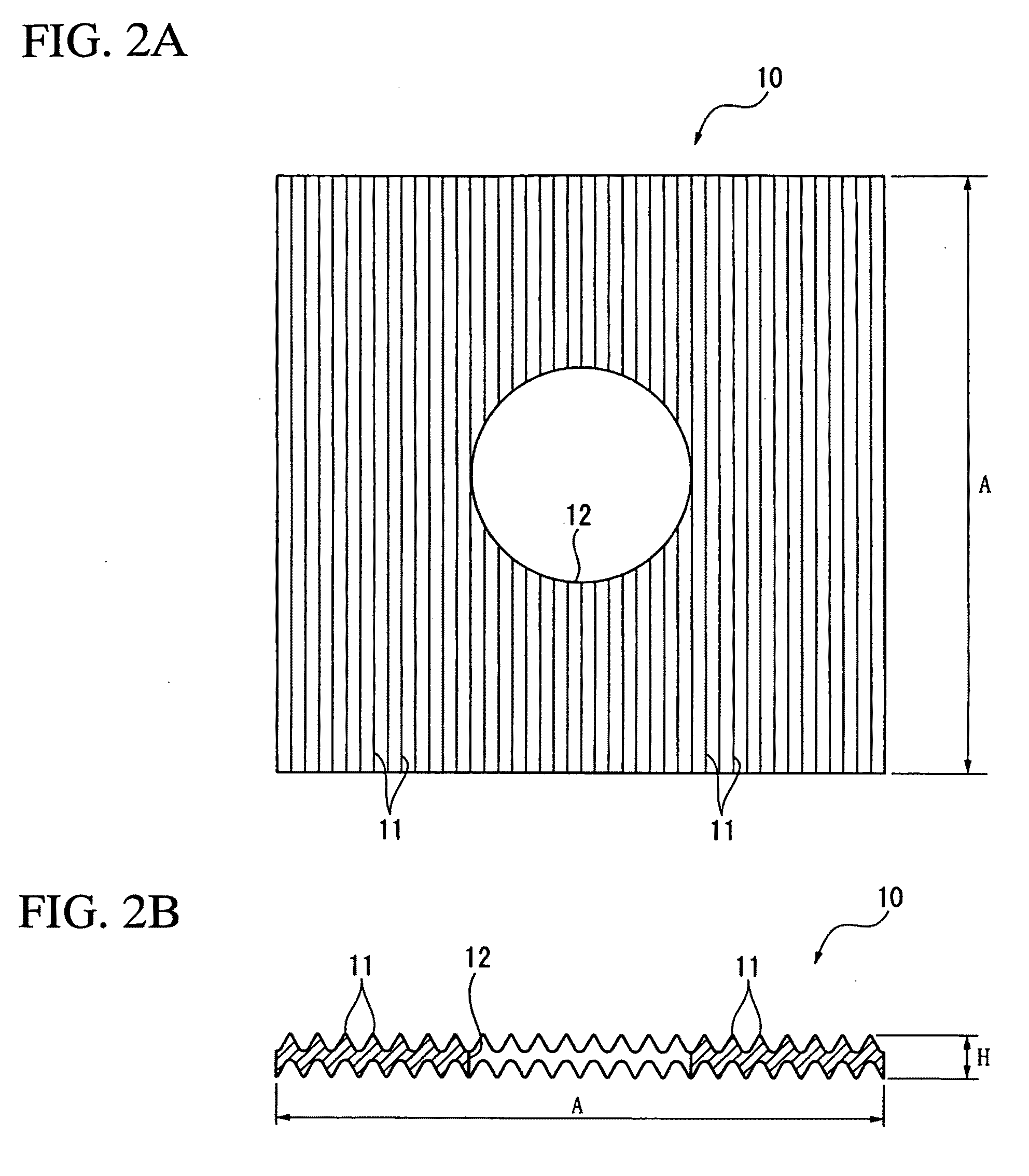
[0127]As illustrated in FIG. 15, the friction-joining steel plate 10A of Embodiment 1 is such that the projected streaks 11 are formed symmetrically on the front face and the back face, a space (S) between adjacent projected streaks 11 is set to be about 1.5 mm, and a distance (H) between the tip ends of the projected streaks 11 on the front face and the back face is set to be about 1.5 mm. Further, in the friction-joining steel plate 10a, a tip angle (θ) of the projected streaks 11 is set to be about 90° and a radius (R1) of the tip end portion of the projected streaks 11 is set to be 0.1 mm or less (about 0.1 mm), and a radius (R2) of a recess between the projected streaks 11 is set to be 0...

embodiment 2

[0129]FIG. 17 is a photo showing a friction-joining steel plate of Embodiment 2. FIG. 18 is a sectional view illustrating the friction-joining steel plate 10B of Embodiment 2. FIG. 19 is a graph illustrating the test results obtained by using the friction-joining steel plate 10B of Embodiment 2.

[0130]As illustrated in FIG. 18, the friction-joining steel plate 10B of Embodiment 2 is such that the projected streaks 11 are formed symmetrically on the front face and the back face, a space (S) between adjacent projected streaks 11 is set to be about 0.8 mm, and a distance (H) between the tip ends of the projected streaks 11 on the front face and the back face is set to be about 1.5 mm. Further, in the friction-joining steel plate 10b, a tip angle (θ) of the projected streaks 11 is set to be about 75° and a radius (R1) of the tip end portion of the projected streaks 11 is set to be 0.1 mm or less (about 0.1 mm), and a radius (R2) of a recess between the projected streaks 11 is set to be 0...


PUM

PropertyMeasurementUnit
Angleaaaaaaaaaa
Angleaaaaaaaaaa
Lengthaaaaaaaaaa

Abstract

Since a portion of projected streaks on a friction-joining steel plate 10 is provided with a Vickers hardness which is at least 3 times greater than that on the surface of steel plates IA and IB, the projected streaks are allowed to more easily enter into the steel plates IA and IB, and since a frictional resistance derived from a mechanical slip resistance of the thus entered projected streaks acts between the steel plates IA and IB, a marked increase is obtained in the friction coefficient between the steel plates IA and IB via the friction-joining steel plate 10. Consequently, a friction-joining structure is constituted by a slip resistance mechanism which can be easily validated from a theoretical or an experimental point of view and is also small in variance of the friction coefficient. Therefore, a friction coefficient used in design can be set at a high value with high accuracy to realize a rational design.

Description

TECHNICAL FIELD[0001]The present invention relates to a friction-joining steel plate and a friction-joining structure, and more particularly to a friction-joining steel plate inserted between steel products to be joined which ate mutually friction-joined and a friction-joining structure in which the friction-joining steel plate is used.[0002]Priority is claimed on Japanese Patent Application No. 2006-107457, filed Apr. 10, 2006, and Japanese Patent Application No. 2007-49013, filed Feb. 28, 2007, the content of which is incorporated herein by reference.BACKGROUND ART[0003]Conventionally, in the fields of architecture and civil engineering, friction joining is generally conducted in which fastening devices such as high-strength bolts are used to fasten steel products to be joined, which are then mutually joined by utilizing a frictional resistance resulting from the compressive force derived from the fastening devices, thereby providing a joining structure for steel products constitu...

Claims


Application Information

Patent Timeline
IPC IPC(8): B32B3/30B32B15/01
CPCF16B2/005F16B5/02F16B43/00Y10T428/12201Y10T428/24942Y10T428/12451Y10T428/24983Y10T428/12965Y10T428/12361Y10T428/12347
Inventor WATANABE, ATSUSHITOMIMOTO, ATSUSHI
Owner NIPPON STEEL & SUMIKIN ENG CO LTD
Why Eureka
Try Eureka