Pneumatic massage apparatus

a technology of pneumatic massage and apparatus, applied in the field of pneumatic massage apparatus, can solve problems such as noise, and achieve the effect of low operation noise, efficient arrangement and connection of electromagnetic valves

Active Publication Date: 2009-09-24
NITTO KOHKI CO LTD
View PDF24 Cites 5 Cited by
  • Summary
  • Abstract
  • Description
  • Claims
  • Application Information

AI Technical Summary

Benefits of technology

[0028]As described above, the present invention can provide a pneumatic massage apparatus with low operation noise. Further, it is possible to efficiently arrange and connect the electromagnetic valves and the hose with respect to the pneumatic massage device.

Problems solved by technology

Therefore, the armature is attracted to and hits against the solenoid, which causes impact noise.

Method used


Image

  • Pneumatic massage apparatus
  • Pneumatic massage apparatus
  • Pneumatic massage apparatus

Examples


Embodiment Construction

[0037]A pneumatic massage apparatus 10 according to an embodiment of the present invention will now be described with reference to the accompanying drawings.

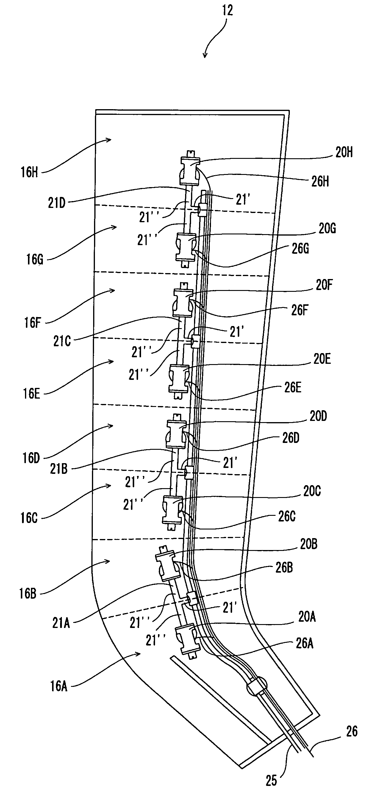
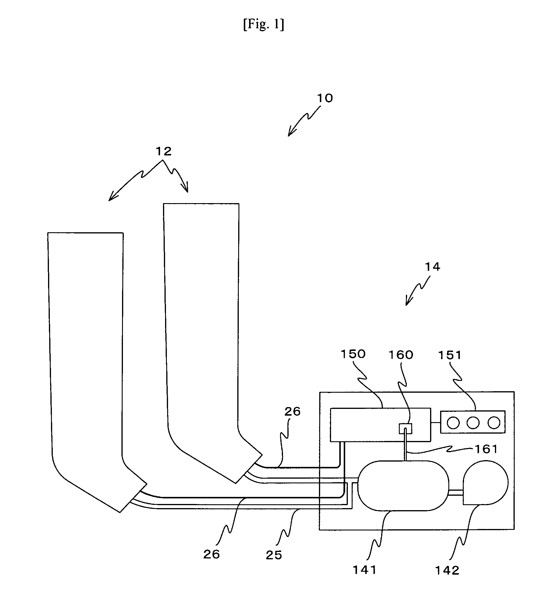
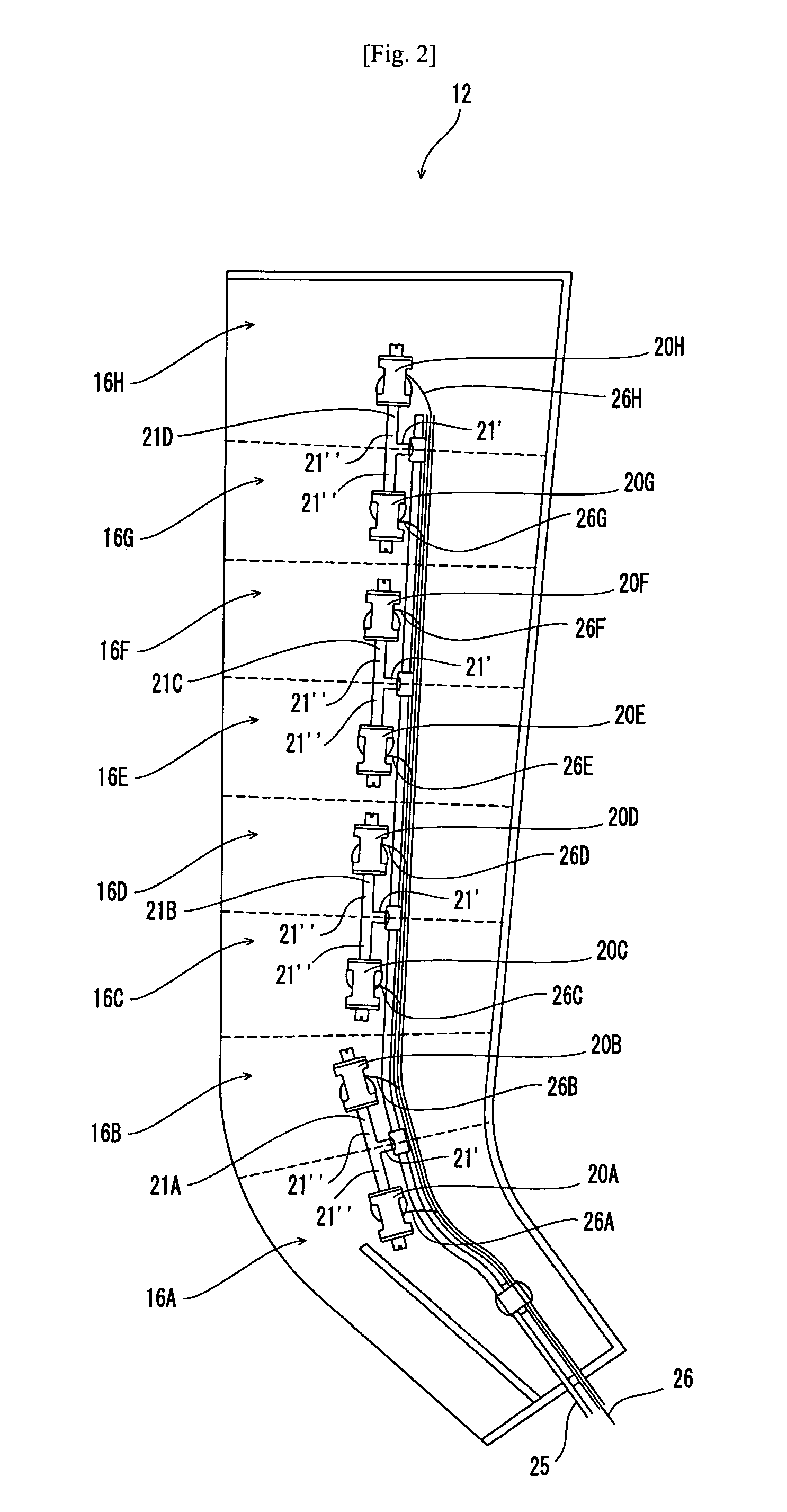
[0038]As shown in FIG. 1, the pneumatic massage apparatus 10 includes a pair of massage devices 12 which are worn around the left and right lower limbs of a user, and a massage apparatus main unit 14 which is placed on a floor or the like adjacent to the user wearing the massage devices. The massage devices 12 and the massage apparatus main unit 14 are connected through a pressurized air supply hose 25 and a plurality of control signal lines 26.

[0039]The massage apparatus main unit 14 includes a tank 141 for maintaining pressurized air in a stable state, a pump 142 for feeding air to the tank 141, a control unit 150 for mainly controlling the operation of each electromagnetic valve, and an operation panel 151 by which a user or the like gives instructions for operation of the pneumatic massage apparatus 10. The control unit 150 ...


PUM


Abstract

A light-weight pneumatic massage apparatus with low operation noise is provided. This apparatus includes a pneumatic massage device (12) and a pump (142) separated from the massage device. The apparatus further includes electromagnetic valves (20, 96) for controlling supply and discharge of pressurized air to and from air chambers (16A to 16H) of the pneumatic massage device (12), respectively. Each of the electromagnetic valves includes a displaceable valve member (46) having an armature (74), and a solenoid (44) for attracting the armature to move the displaceable valve member when a voltage is applied to the solenoid. The apparatus further includes an electromagnetic valve control unit (150) which controls a voltage supplied to the solenoid to open the electromagnetic valves such that the voltage increases from V1 to V2 gradually with the passage of time T1. The armature is attracted onto the end surface of the solenoid within the time period T1. Then, in a state in which the voltage is reduced to V3, the armature is maintained attracted onto the solenoid to keep the open state. After that, voltage supply is stopped to close the valve.

Description

TECHNICAL FIELD[0001]The present invention relates to a pneumatic massage apparatus which has a plurality of air chambers, and which provides a massage effect while expanding and contracting the air chambers by controllably supplying and discharging pressurized air thereto and therefrom.BACKGROUND ART[0002]Generally, a pneumatic massage apparatus has a plurality of air chambers, and provides a massage effect while expanding and contracting the air chambers by supplying pressurized air from a pump to the air chambers and discharging the pressurized air from the air chambers. Supply and discharge of pressurized air is controlled by means of an electromagnetic valve using a solenoid. In the electromagnetic valve, a voltage is applied to the solenoid to attract an armature attached to a displaceable valve member, whereby the displaceable valve is moved to open and close the electromagnetic valve. Therefore, the armature is attracted to and hits against the solenoid, which causes impact ...

Claims


Application Information

Patent Timeline
Patent Type & Authority Applications(United States)
IPC IPC(8): A61H15/00
CPCA61H9/0078A61H2201/50A61H2205/10A61H2201/5071A61H2201/5002A61H9/00A61H9/0071
Inventor NAKAO, HARUKIKAWASHIMA, HIROKI
Owner NITTO KOHKI CO LTD
Why Eureka
Try Eureka