

Tandem master cylinder
- Summary
- Abstract
- Description
- Claims
- Application Information
AI Technical Summary
Benefits of technology
Problems solved by technology
Method used
Image

Examples
first embodiment
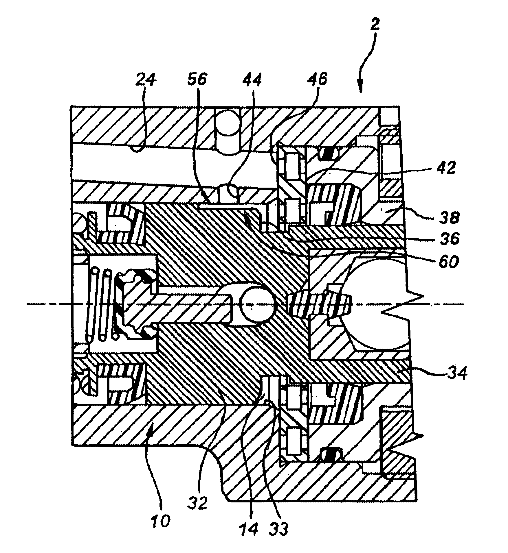
FIGS. 2A, 2B and 2C show a first example of a master cylinder according to the present invention comprising a body 2 of longitudinal axis X pierced with a bore 4 in which there is mounted to slide with sealing at least one hydraulic piston 10 actuated by an actuating rod connected to a brake pedal (neither depicted). The sliding of the piston 10 is sealed, for example, by a lip seal 9 mounted fixedly on a front end of the piston 10. The piston 10 divides the bore 4 into a supply chamber 14 supplied with brake fluid by a brake fluid reservoir (not depicted) by means of a supply duct 24, and a work chamber 16 in communication in normal operation with brakes arranged at the wheels (not depicted). The piston 10 comprises, toward the front, a piston head 32 and, toward the rear, a piston shank 34, the sliding of the piston 10 being guided by the guiding of the piston shank 34 by means of a guide ring 38 mounted with sealing in the body of the master cylinder by means for example of an O-...
second embodiment
FIG. 4 shows a detail of a master cylinder according to the present invention, comprising a body 2 of longitudinal axis X pierced with a bore 4 in which there is mounted to slide with sealing at least one hydraulic piston 10 actuated by an actuating rod connected to a brake pedal (neither depicted). The sliding of the piston 10 is sealed for example by means of a lip seal (not depicted) mounted fixedly on a front end of the piston 10. The piston 10 dividing the bore 4 into a supply chamber (not depicted) supplied with brake fluid by a brake fluid reservoir (not depicted) by means of a supply duct 24, and a supply work chamber (not depicted) in communication in normal operation with brakes arranged at the wheels (not depicted). Toward the front the piston 10 has a piston head 32 and toward the rear it has a piston shank 34, the sliding of the piston 10 being guided by the guiding of the piston shank 34 by means of a guide ring 38 mounted with sealing in the body of the master cylinde...
fourth embodiment
FIGS. 9A, 9B and 9C show a master cylinder according to the present invention, comprising a body 2 of longitudinal axis X pierced with a bore 4 in which there is mounted to slide with sealing at least one hydraulic piston 10 actuated by an actuating rod connected to a brake pedal (neither depicted). The sliding of the piston 10 is sealed for example by means of a lip seal 9 mounted fixedly on a front end of the piston 10. The piston 10 dividing the bore 4 into a supply chamber 14 supplied with brake fluid by a brake fluid reservoir (not depicted) by means of a supply duct 24, and a work chamber 16 in communication in normal operation with brakes arranged at the wheels (not depicted). Toward the front the piston 10 has a piston head 32 and toward the rear it has a piston shank 34, the sliding of the piston 10 being guided by the guiding of the piston shank 34 by means of a guide ring 38 mounted with sealing in the body of the master cylinder by means for example of an O-ring seal 45 ...
PUM
 Abstract
Description
Claims
Application Information