
Pin Centering Guide with Goniometer

a centering guide and goniometer technology, applied in the field of pin centering guide with goniometer, can solve the problems of inconvenient use, inconvenient use, and difficulty in re-revision of primary total hip prosthesis, and achieve the effects of avoiding fractures, loosening and impinging, and accurate pin placemen

Active Publication Date: 2009-09-24
MICROPORT ORTHOPEDICS HLDG INC
View PDF6 Cites 26 Cited by
  • Summary
  • Abstract
  • Description
  • Claims
  • Application Information

AI Technical Summary

Benefits of technology

[0010]It is another object of the invention to provide femoral pin guide placement instruments that determine component position, and avoid fractures, loosening and impingement.
[0011]It is another object of the invention to provide femoral guide pin placement instruments that enable accurate pin placement to be achieved the first time, with no need to check or adjust.
[0012]It is another object of the invention to provide femoral guide pin placement instruments and related techniques of use that are simple, reliable and cope with all cases e.g. large osteophytes, abnormal varus / valgus or anteversion.

Problems solved by technology

However, over time, the implant may wear out or loosen.
Successful revision of a primary total hip prosthesis can be challenging because there is less natural bone to work with, due to the previous removal of the head and neck and neck, and the loss of bone in the area of the primary implant.
However, placement by eye can also lead to inaccuracy or inconsistency in pin placement, and therefore to less than optimal results, particularly when practiced by an inexperienced surgeon.
However, the femoral neck clamp does not guide varus / valgus or anteversion.

Method used


Image

  • Pin Centering Guide with Goniometer
  • Pin Centering Guide with Goniometer
  • Pin Centering Guide with Goniometer

Examples


Embodiment Construction

[0029]In the following detailed description of the preferred embodiments, reference is made to the accompanying drawings which form a part hereof, and in which are shown by way of illustration specific embodiments in which the invention may be practiced. It is to be understood that other embodiments may be utilized and structural changes may be made without departing from the scope of the present invention.

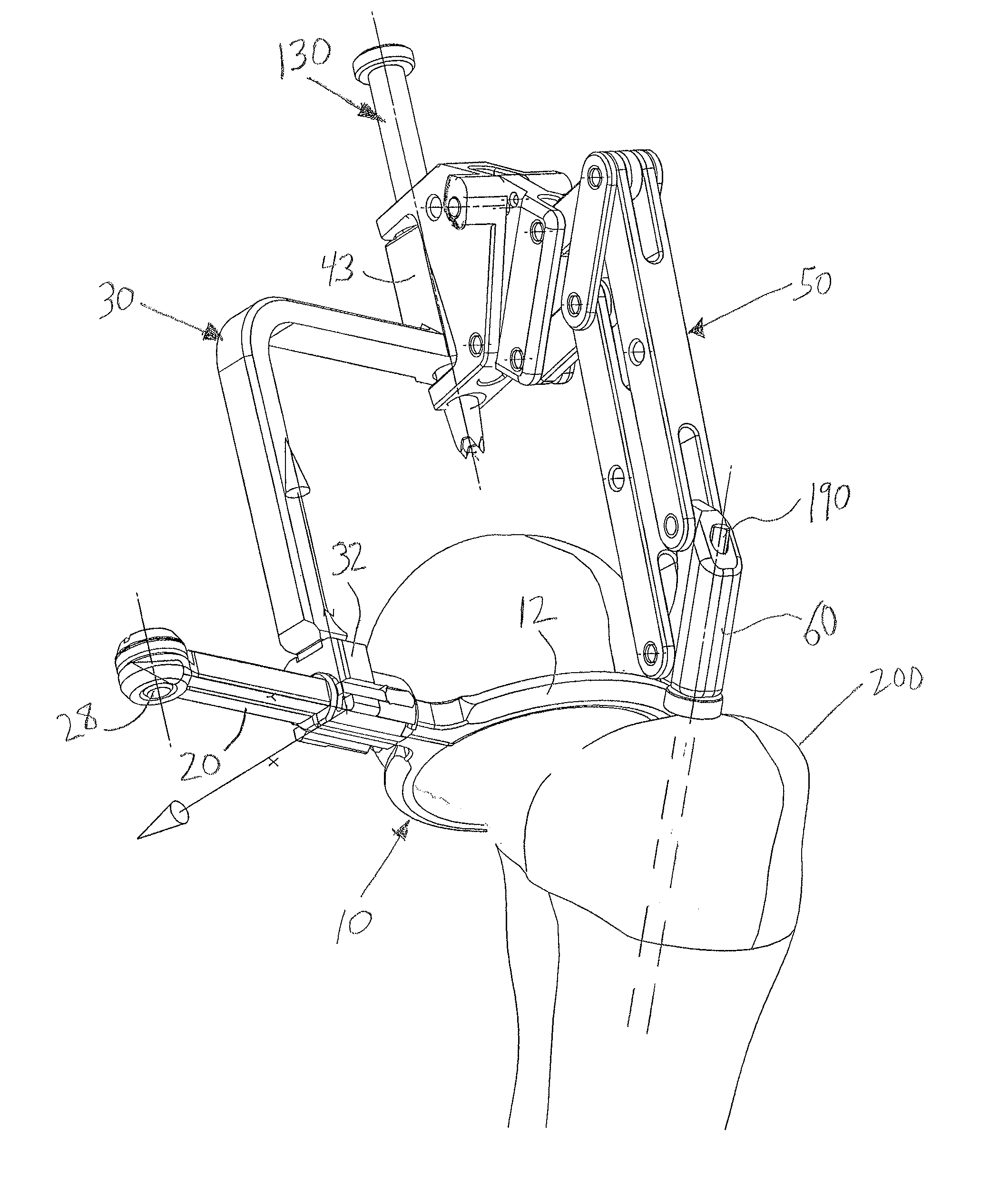
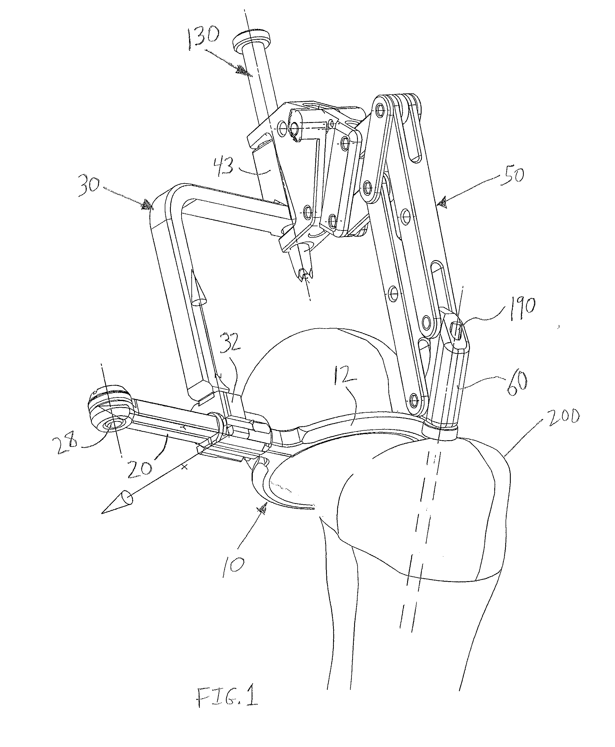
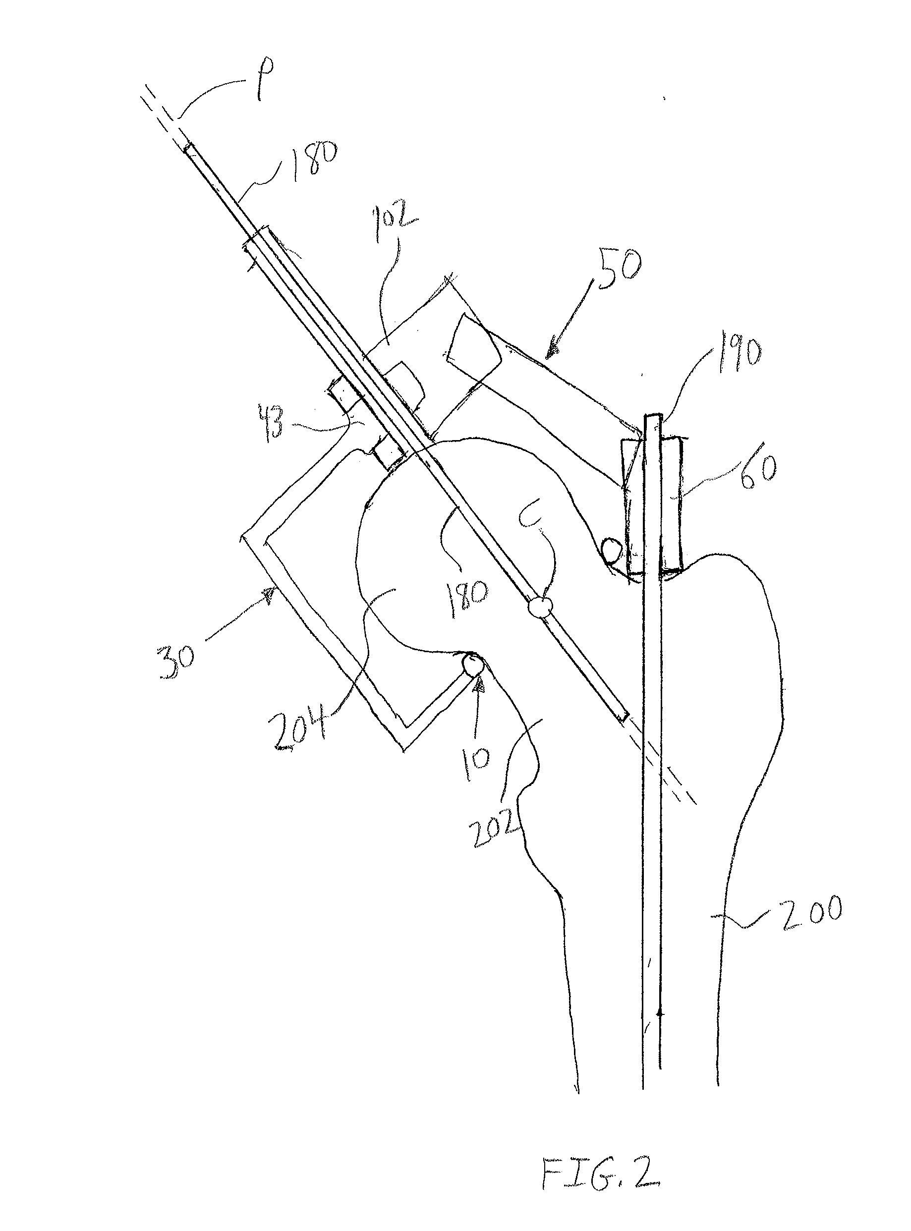
[0030]As shown in FIG. 1, the invention is an assembly for placing a guide pin 180 in a femoral neck 202 of a patient for subsequent use in resurfacing a femoral head 204. The assembly is configured so as to enable the orientation of the guide pin 180 to be established with reference to a medullary guide wire 190. The assembly includes, generally, a femoral neck clamp 10, a pin guide 30, and a goniometer 50. A bushing 130 links the pin guide 30 to the goniometer 50. As indicated in the representational view of FIG. 2, the femoral neck clamp 10 is configured to define a pin point C...


PUM


Abstract

An instrument assembly for placing a guide pin in a femoral neck of a patient with reference to a medullary guide wire for use in resurfacing a femoral head. The assembly comprises a femoral neck clamp configured to define a femoral neck center. A pin guide attaches to the femoral neck clamp. A pin guide portion of the pin guide is configured to define a pin guide path passing through the neck center. The pin guide portion is linked to pin guide engagement portion of an adjustable goniometer. The goniometer maintains a specific angle between the pin guide engagement portion and the medullary guide wire, and in turn maintains the pin guide path at the specific angle.

Description

CROSS REFERENCE TO RELATED APPLICATIONS[0001]This application is a continuation of, claims priority to, and incorporates by reference U.S. Provisional Patent Application No. 61 / 012,090, filed Dec. 7, 2007, which is pending.STATEMENT REGARDING FEDERALLY SPONSORED RESEARCH[0002]Not applicableFIELD OF THE INVENTION[0003]The present invention relates to the use of guides for placement of guide wires or pins in orthopedic surgery, and more particularly to the use of instruments for the placement of a guide pin in a femoral neck for use in femoral head resurfacing.BACKGROUND OF THE INVENTION[0004]In total hip arthroplasty, the head and neck of the femur are removed and replaced with a femoral stem prosthesis, along with a matching cup in the acetabulum. Barring complications, a total hip replacement provides a patient with a hip joint that functions much like the natural hip joint, typically for a 20 to 30 year period. However, over time, the implant may wear out or loosen. In such cases,...

Claims


Application Information

Patent Timeline
Patent Type & Authority Applications(United States)
IPC IPC(8): A61B17/58
CPCA61B17/72A61B17/175
Inventor MURRAY, DAVID W.
Owner MICROPORT ORTHOPEDICS HLDG INC
Learn More