Engine control device for working vehicle

a technology for working vehicles and control devices, applied in electrical control, program control, instruments, etc., can solve the problems of poor balance between traction force and lift force, complicated control, lack of reliability, etc., and achieve the effect of increasing traction for

Active Publication Date: 2009-09-24
KOMATSU LTD
View PDF9 Cites 17 Cited by
  • Summary
  • Abstract
  • Description
  • Claims
  • Application Information

AI Technical Summary

Benefits of technology

[0011]It is an object of the present invention to achieve appropriate balance between the traction force and the lift force with simple control and further enhance workability.
[0028]In this case, in the similar way to the device of the sixth invention, it is possible to achieve larger traction force by reducing the maximum throttle amount to be a small value only when the large traction force is needed.

Problems solved by technology

Therefore, there is a problem that control tends to be complicated and lacks reliability.
Therefore, balance between the traction force and the lift force is worse than the balance regulated by the expert operator's accelerator operation.
Because of this, there is a problem that operator's intended balance between the traction force and the lift force is not achieved.

Method used


Image

  • Engine control device for working vehicle
  • Engine control device for working vehicle
  • Engine control device for working vehicle

Examples


Embodiment Construction

Overall Configuration

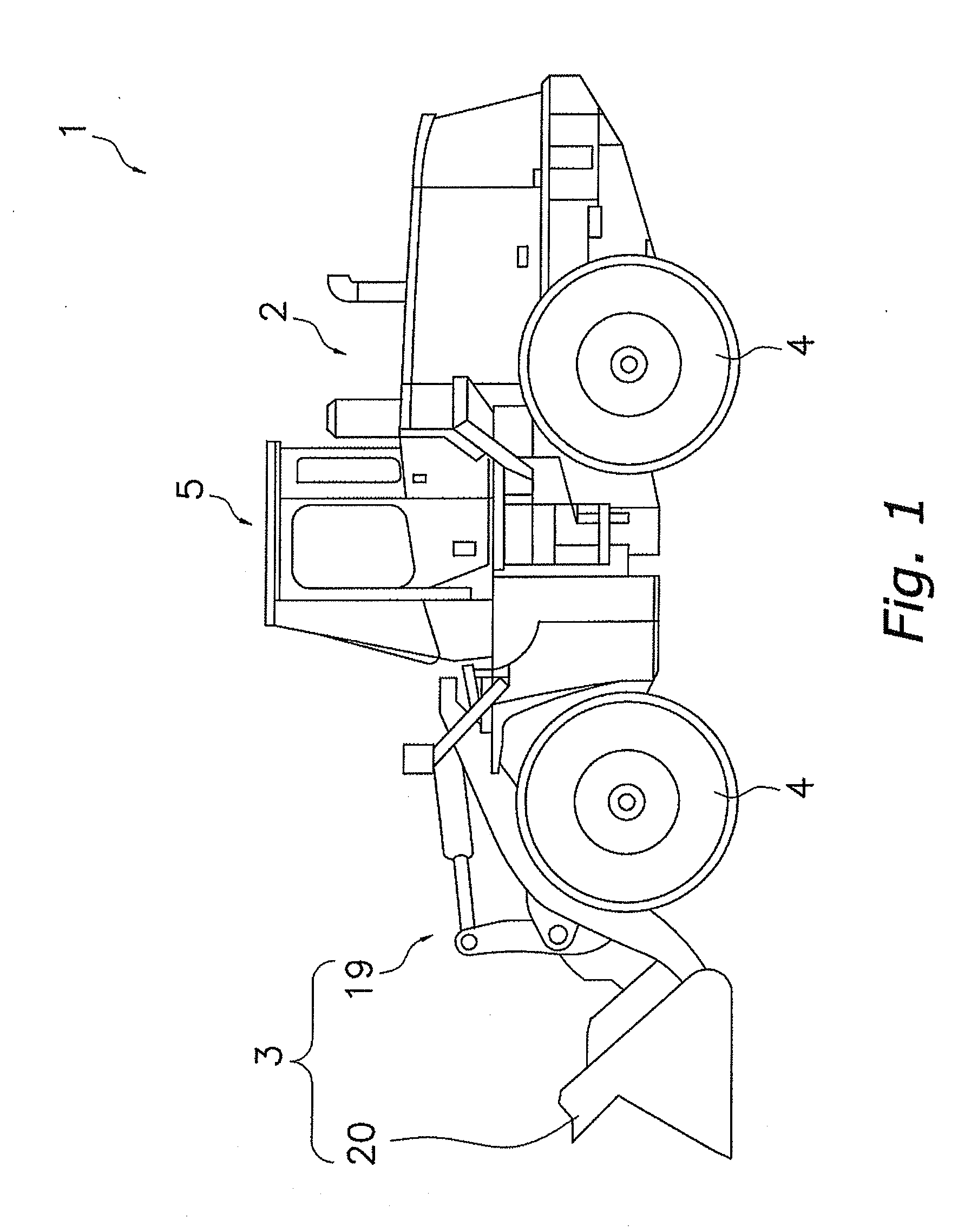
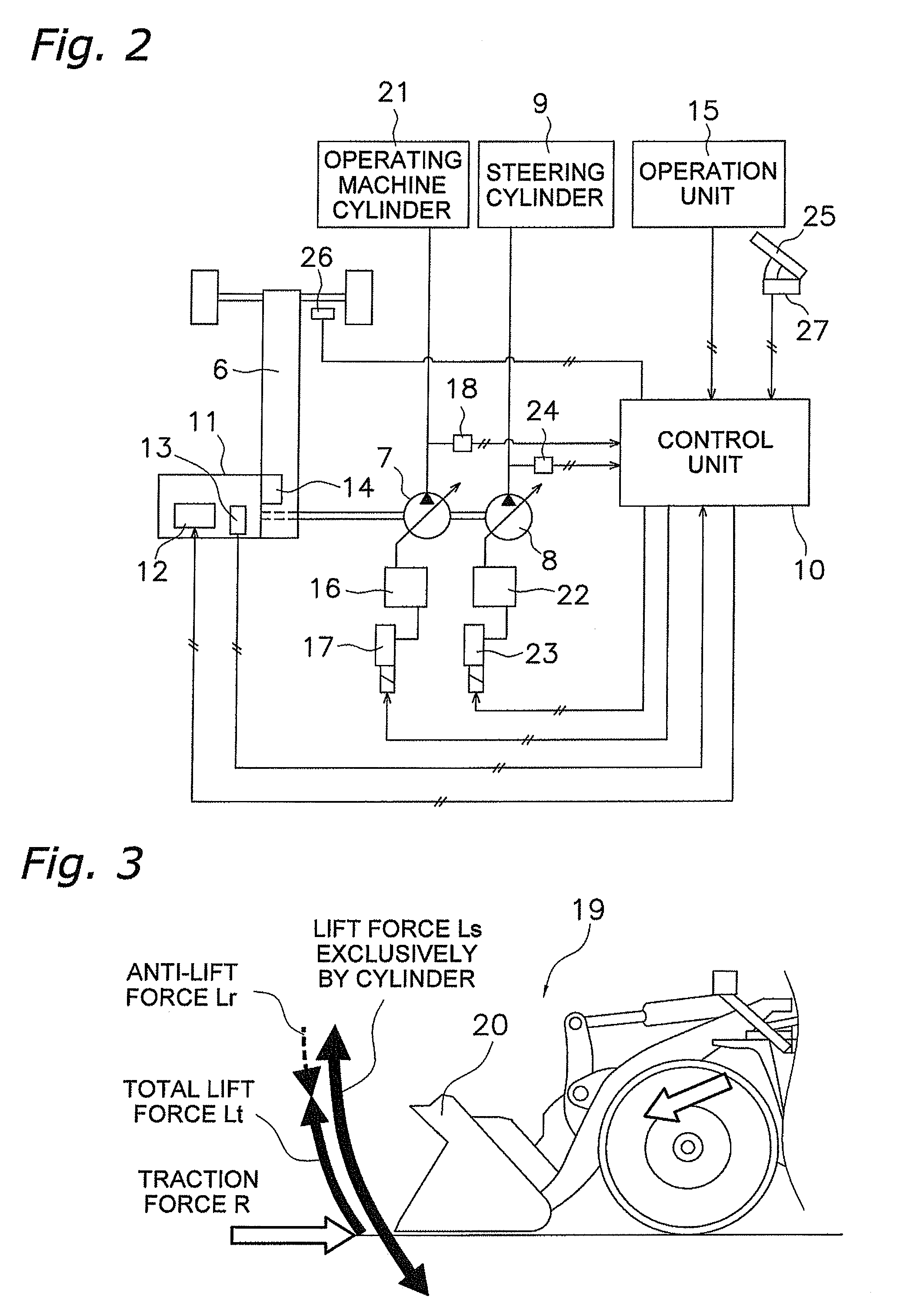
[0035]FIG. 1 illustrates a wheel loader 1 of an embodiment of the present invention. The wheel loader 1 includes a vehicle body 2, a working machine 3 attached to the front part of the vehicle body 2, four tires 4 that case the vehicle body 2 to travel by their rotation while they support the vehicle body 2, and a working room 5 mounted on the top of the vehicle body 2. In addition, as illustrated in FIG. 2, the vehicle body 2 is provided with an engine 11, a transmission 6, a working machine hydraulic pump 7, a steering hydraulic pump 8, a steering cylinder 9, a control unit 10, and the like. Output torque generated in the engine 11 is distributed to the transmission 6, the working machine hydraulic pump 7, the steering hydraulic pump 8, and the like, and thus the output torque works for driving the working machine 3 and / or works as the driving force during traveling. Note that FIG. 1 is an external lateral view of the wheel loader 1, and FIG. 2 is a schematic ...


PUM


Abstract

This engine control device of a self-propelled working vehicle is an engine control device of a self-propelled working vehicle that includes a working machine hydraulic pump for driving a working machine, and includes a vehicle velocity detection section configured and arranged to detect a vehicle velocity and a traction force control section. The traction force control section is configured to reduce the traction force by limiting the maximum throttle amount when the vehicle velocity is less than or equal to predetermined velocity based on the result detected by the vehicle velocity detection section.

Description

CROSS-REFERENCE TO RELATED APPLICATIONS[0001]This U.S. National stage application claims priority under 35 U.S.C. §119(a) to Japanese Patent Application No. 2006-002850, filed in Japan on Jan. 10, 2006. The entire disclosure of Japanese Patent Application No. 2006-002850 is hereby incorporated herein by reference.FIELD OF THE INVENTION[0002]The present invention relates to an engine control device, especially to an engine control device of a self-propelled working vehicle including a working machine hydraulic pump for driving a working machine.BACKGROUND ART[0003]A wheel loader as a self-propelled working vehicle is configured to obtain the driving force for a carrier and the driving force for a working machine from a single engine. Specifically, the driving force for a carrier of the wheel loader is obtained by a so-called HST hydraulic traveling device, or is obtained through a torque converter. Also, a hydraulic cylinder for driving a front working machine is driven by a hydrauli...

Claims


Application Information

Patent Timeline
Patent Type & Authority Applications(United States)
IPC IPC(8): G06F19/00F02D29/02F02D29/04F02D41/04
CPCF02D29/04F02D29/02
Inventor MATSUYAWA, NOBUO
Owner KOMATSU LTD
Why Eureka
Try Eureka