Multi-Point Measuring Method and Surveying Device

a multi-point measuring and surveying technology, applied in the field of multi-point measuring methods and surveying devices, can solve the problems of difficult measurement for long distances, high cost, and high cost, and achieve the effect of higher magnification

Active Publication Date: 2009-10-01
KK TOPCON
View PDF11 Cites 31 Cited by
  • Summary
  • Abstract
  • Description
  • Claims
  • Application Information

AI Technical Summary

Benefits of technology

[0007]Also, the present invention provides a surveying device, which comprises a telescope unit having a first image pickup unit for acquiring a wide-angle image and a second image pickup unit for acquiring a telescopic image with higher magnification than the wide-angle image, a distance measuring unit for performing distance measurement by projecting a distance measuring light and by receiving a light reflected from an object to be measured, an angle measuring unit for detecting a horizontal angle and a vertical angle of the telescope unit, a drive unit for rotating and driving the telescope unit in a horizontal direction and in a vertical direction, and a control device for controlling image pickup of the first image pickup unit and the second image pickup unit and for controlling the drive unit based on the results of detection from the angle measuring unit, wherein the control device synthesizes a panoramic image by connecting the wide-angle image obtained by the first image pickup unit, sets up a scheduled measuring point by edge processing of the wide-angle image, and extracts a measuring point corresponding to the scheduled measuring point in the telescopic image by scanning the sche...

Problems solved by technology

However, the measurement is performed by manual operation for each point, and much time is required to measure a multiple of points on rock, face of slope, etc. and to acquire planar data.
Therefore, in the data processing after measurement, in order to extract the measurement data of the portions needed for the preparati...

Method used


Image

  • Multi-Point Measuring Method and Surveying Device
  • Multi-Point Measuring Method and Surveying Device
  • Multi-Point Measuring Method and Surveying Device

Examples


Embodiment Construction

[0018]Detailed description will be given below on the best mode for carrying out the present invention by referring to the drawings.

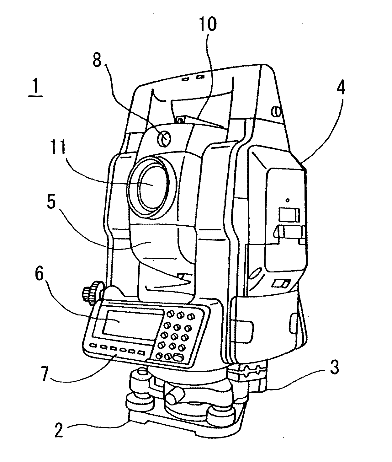
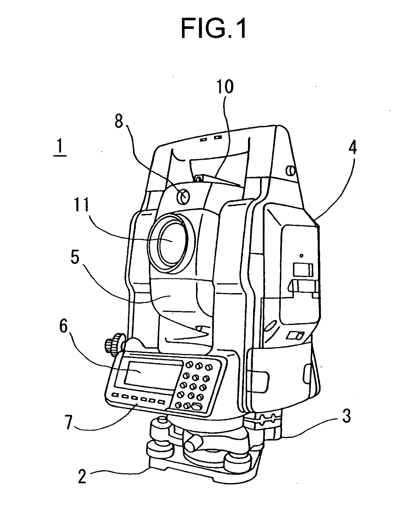
[0019]FIG. 1 shows a surveying device 1, to which the present invention is applied. The surveying device 1 in use is a total station, for instance, in which a pulsed laser beam is projected to a measuring point. The pulsed light reflected from the measuring point, and a distance is measured for each pulse. The results of the distance measurement are averaged, and the distance can be measured with high accuracy.

[0020]The surveying device primarily comprises a leveling unit 2 to be mounted on a tripod (not shown), a base unit 3 to be attached to the leveling unit 2, a frame unit 4 attached on the base unit 3 so as to be rotated around a vertical axis, and a telescope unit 5 attached on the frame unit 4 so as to be rotated around a horizontal axis. A sight 10 for setting approximate collimating direction of the surveying device 1 is mounted on the surveyin...


PUM


Abstract

There are provided a telescope unit (5) having a first image pickup unit for acquiring a wide-angle image and a second image pickup unit for acquiring a telescopic image with higher magnification than the wide-angle image, a distance measuring unit for performing distance measurement by projecting a distance measuring light and by receiving a light reflected from an object to be measured, an angle measuring unit for detecting a horizontal angle and a vertical angle of the telescope unit, a drive unit for rotating and driving the telescope unit in a horizontal direction and in a vertical direction, and a control device for controlling image pickup of the first image pickup unit and the second image pickup unit and for controlling the drive unit based on the results of detection from the angle measuring unit, wherein the control device synthesizes a panoramic image by connecting the wide-angle image obtained by the first image pickup unit, sets up a scheduled measuring point by edge processing of the wide-angle image, and extracts the measuring point corresponding to the scheduled measuring points in the telescopic image by scanning the scheduled measuring point and acquiring the telescopic image by the second image pickup unit with respect to scheduled measuring points, and distance measurement is performed on the measuring point.

Description

FIELD OF THE INVENTION[0001]The present invention relates to a multi-point measuring method and a surveying device, which enable measurement of a multiple of points on an object in wide range.BACKGROUND ART[0002]In the past, the so-called non-prism measuring instrument has been known, in which a pulsed laser beam is projected for scanning an object to be measured and a distance measurement is performed based on a light reflected from the object to be measured, and three-dimensional measurement is performed on the object to be measured based on the value of the measured distance thus obtained and based on an elevation angle and a horizontal angle at a measuring point. In recent years, there has been a three-dimensional measuring instrument called a laser scanner in which measurement on a multiple of points can be performed at high speed.[0003]The non-prism measuring instrument can perform measurement for long distance with high measurement accuracy and can measure reliably on the obj...

Claims


Application Information

Patent Timeline
IPC IPC(8): G01C3/04G06K9/00H04N7/00G01C7/00G01C15/00
CPCG01C15/002
Inventor OHTOMO, FUMIOOTANI, HITOSHIKANEKO, JUNKIANAI, TETSUJINAGASHIMA, TERUKAZU
Owner KK TOPCON
Why Eureka
Try Eureka