Fuel supply pipe device and fuel injection device having the same

Inactive Publication Date: 2009-10-01
DENSO CORP
View PDF11 Cites 12 Cited by
  • Summary
  • Abstract
  • Description
  • Claims
  • Application Information

AI Technical Summary

Benefits of technology

[0005]In view of the foregoing and other problems, it is one object of the present invention to produce a fuel supply pipe device, which is configured to be mounted with fuel injectors and capable of stabilizing quantity of fuel supplied to the fuel injectors. It is one object to produce a fuel supply

Problems solved by technology

Accordingly, a mounting work of the fuel injection valves to the fuel delivery pipe, an exchanging work of the fuel injection valves in a case of malfunction, and electric wiring to the fuel injection valves are difficult in the twin injection engine.
In addition, since the number of the fuel injection valves mounted to the fuel delivery pipe becomes twice, load exerted to the fuel delivery pipe increases, and therefore mountability of the fuel delivery pipe to the internal combustion engine may be impaired.
In addition, pulsation may be significantly caused in fuel supplied from the fuel delivery pipe to the

Method used


Image

  • Fuel supply pipe device and fuel injection device having the same
  • Fuel supply pipe device and fuel injection device having the same
  • Fuel supply pipe device and fuel injection device having the same

Examples


Example

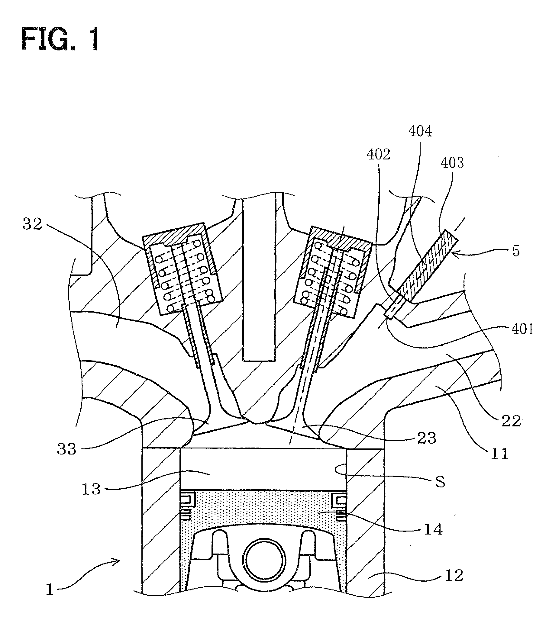
[0032]A fuel supply pipe device according to the present first embodiment will be described with reference to drawings. As shown in FIGS. 1 to 5, a fuel delivery pipe 4 (FIG. 3) according to the present first embodiment is used for an internal combustion engine 1 for supplying fuel to each of fuel injection valves (injectors) 5. In the internal combustion engine 1, each of cylinders S has two intake valves 23 each correspondingly provided with each of two injectors 5. According to the present embodiment, the engine 1 is an inline four-cylinder engine in which four cylinders S including a first cylinder S1 to a fourth cylinder S4 are located in series.

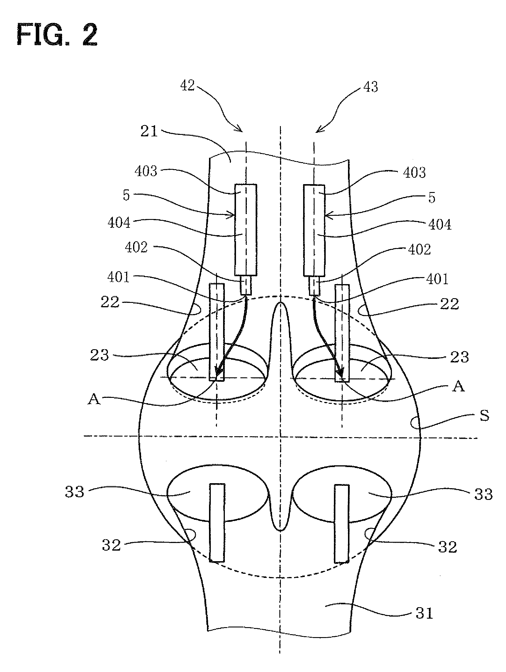
[0033]As follows, the structure of the engine 1 will be described in detail. As shown in FIGS. 1, 2, in the engine 1, each cylinder S is provided with two intake ports 22, the two intake valves 23, and two injectors 5. Each of the two intake ports 22 opens to a combustion chamber 13. Each of the two intake valves 23 opens and closes cor...

Example

Second Embodiment

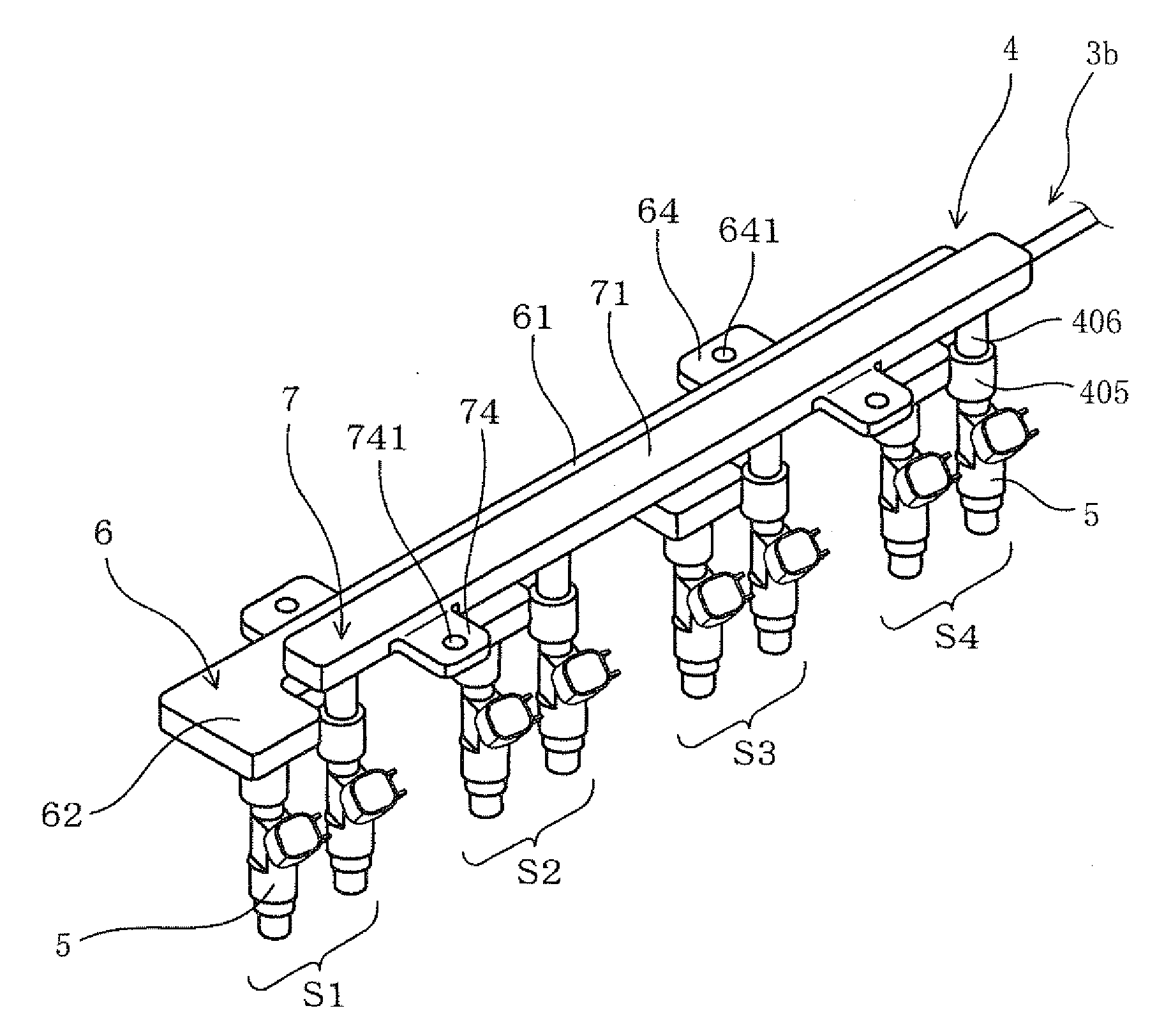
[0046]In the present second embodiment, as shown in FIGS. 6 to 8, the fuel delivery pipe 4 including the first fuel delivery pipe 6 and the second fuel delivery pipe 7 has a different structure from that in the first embodiment. According to the present second embodiment, as shown in FIGS. 6, 7, the first fuel delivery pipe 6 includes the first body portion 61 and the first projections 62. The first body portion 61 is in a substantially linear shape. The first projections 62 protrude from the first body portion 61 perpendicularly to the axial directions of the injectors 5. The first projections 62 have lower surfaces, which respectively have four first fuel holes 63 for supplying fuel to the injectors 5. The four first fuel holes 63 are provided at locations to which the injectors 5 are respectively mounted. The first fuel delivery pipe 6 includes two first stationary portions 64 each projecting from the first body portion 61 to the opposite side of the first projec...

Example

Third Embodiment

[0051]In the present second embodiment, as shown in FIGS. 9 to 11, the fuel delivery pipe 4 including the first fuel delivery pipe 6 and the second fuel delivery pipe 7 has a different structure from that in the above embodiments. According to the present third embodiment, as shown in FIGS. 9, 10, the first fuel delivery pipe 6 includes the first body portion 61 and the first projections 62. The first body portion 61 is in a substantially linear shape. The first projections 62 protrude from the first body portion 61 perpendicularly to the axial directions of the injectors 5. The first projections 62 have lower surfaces, which respectively have four first fuel holes 63 for supplying fuel to the injectors 5. The four first fuel holes 63 are provided at locations to which the injectors 5 are respectively mounted. The first fuel delivery pipe 6 includes two first stationary portions 64 each projecting from the first body portion 61 to the opposite side of the first proje...


PUM


Abstract

An internal combustion engine has multiple cylinders each provided with multiple injectors. A fuel supply pipe device includes multiple fuel passages, which receive fuel through multiple fuel paths and supply the fuel correspondingly to the multiple injectors. The multiple fuel passages are separated respectively from the multiple fuel passages.

Description

CROSS REFERENCE TO RELATED APPLICATIONS[0001]This application is based on and incorporates herein by reference Japanese Patent Applications No. 2008-80112 filed on Mar. 26, 2008 and No. 2008-82750 filed on Mar. 27, 2008.FIELD OF THE INVENTION[0002]The present invention relates to a fuel supply pipe device for supplying fuel to another device such as an internal combustion engine. The present invention further relates to a fuel injection device having the fuel supply pipe device for injecting fuel in an internal combustion engine.BACKGROUND OF THE INVENTION[0003]In a conventional internal combustion engine for an automobile, each cylinder is provided with one fuel injection valve. In such a conventional engine, the same number of fuel injection valves as the number of the cylinders are mounted to a fuel supply pipe device, which supplies fuel to the fuel injection valves. In recent years, for example, JP-A-2005-220875 and JP-A-2006-125333 propose a twin injection engine, in which two...

Claims


Application Information

Patent Timeline
IPC IPC(8): F02M55/02
CPCF02M55/005F02M55/025F02M63/029F02M61/168F02M61/14F02D41/3094F02D2041/3881
Inventor SUGIYAMA, KOUICHIYAMASHITA, YOSHINORIICHIHARA, HIDEAKIOOMURA, HIDEKAZUSUZUKI, HIDEKI
Owner DENSO CORP
Why Eureka
Try Eureka