Humidification in breathing circuits

a technology of breathing circuits and humidification, which is applied in the direction of gaseous fuel burners, inhalators, medical insufflators, etc., can solve the problems of inflammatory airway reactions, humidity deficit, and thick obstructive secretions

Inactive Publication Date: 2009-10-01
CLANCY DERMOT JOSEPH +4
View PDF53 Cites 109 Cited by
  • Summary
  • Abstract
  • Description
  • Claims
  • Application Information

AI Technical Summary

Benefits of technology

[0018]The method may comprise the step of controlling the aerosolisation. Accurate control may be achieved via high speed pulsing of the electrical signal to the aerosol generator. Accurate changes to the pulse frequency will produce accurate and repeatable changes in aerosol output.
[0019]Aerosolisation may be controlled responsive to the flow of ventilation gas in the inspiration line. Greater volumes of gas require proportionally greater fluid flow rate of aerosolised humidifying agent to achieve 100% saturation at a given temperature. The gas flow is measured (via flow or differential pressure sensor) in order to determine and deliver the required volume of humidifying agent to achieve 100% RH. Rapid and accurate measurement of gas flow enables required responsiveness.
[0028]In one arrangement a nebuliser is used to provide humidity at patient side of HME in order to replace humidity losses to allow patients use the HME for longer periods of time.
[0029]Alternatively a nebuliser may be integrated with HME (‘HME booster’) providing humidity to a ventilated patient for longer periods of time possible with conventional HME.

Problems solved by technology

However, following intubation of patients on mechanical ventilation these normal upper airway moisture exchanging structures are bypassed and the burden of moistening the gases is passed to the lower respiratory tract, which is not suited to this task
Such passive heat and moisture exchange systems generally at best only recover 70% of exhaled humidity, creating a humidity deficit, which can create thick obstructive secretions and inflammatory airway reactions in patients with chronic airways disease.
Consequently, passive HME is largely confined to use with patients with relatively healthy lungs.
Some of the problems with known active heated water humidifier systems are that the heated humidifier is bulky, heavy and must be placed close to the ventilator distal to the patient.
In addition, there is a likelihood of rain-out down the ventilator circuit tubing which can block the tubing, saturate the exhalation filter or flood the patient.
This condensate can obstruct the airway, interfere with ventilation and / or increase the growth of pathogens.
These problems can be mitigated by heating the condensate with heated wires but such heated wire systems add to cost and complexity.
In summary active HME systems add expense with only marginal benefits in humidity.
In addition, they add bulk and weight at the airway.

Method used


Image

  • Humidification in breathing circuits
  • Humidification in breathing circuits
  • Humidification in breathing circuits

Examples


Embodiment Construction

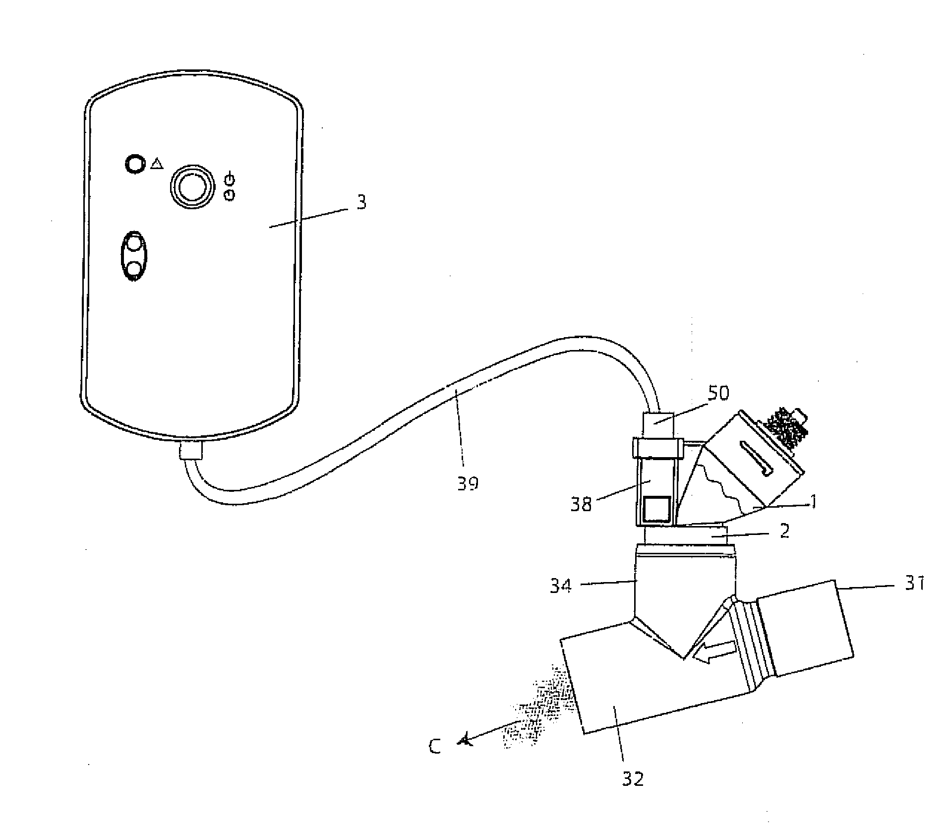
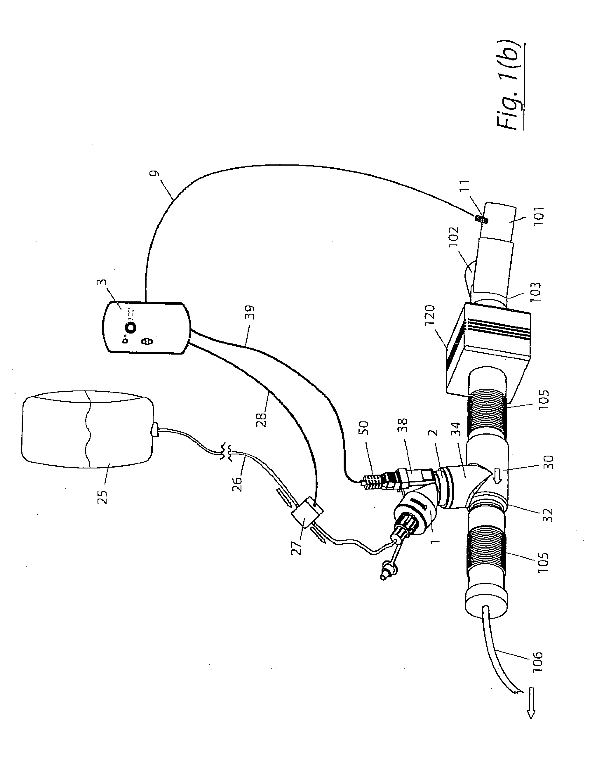
[0072]The invention provides a method and an apparatus for humidifying gas in a ventilator circuit. In the invention a humidifying agent (sterile water or sterile saline) is aerosolised and then delivered to a ventilator circuit coupled to the respiratory system of a patient.

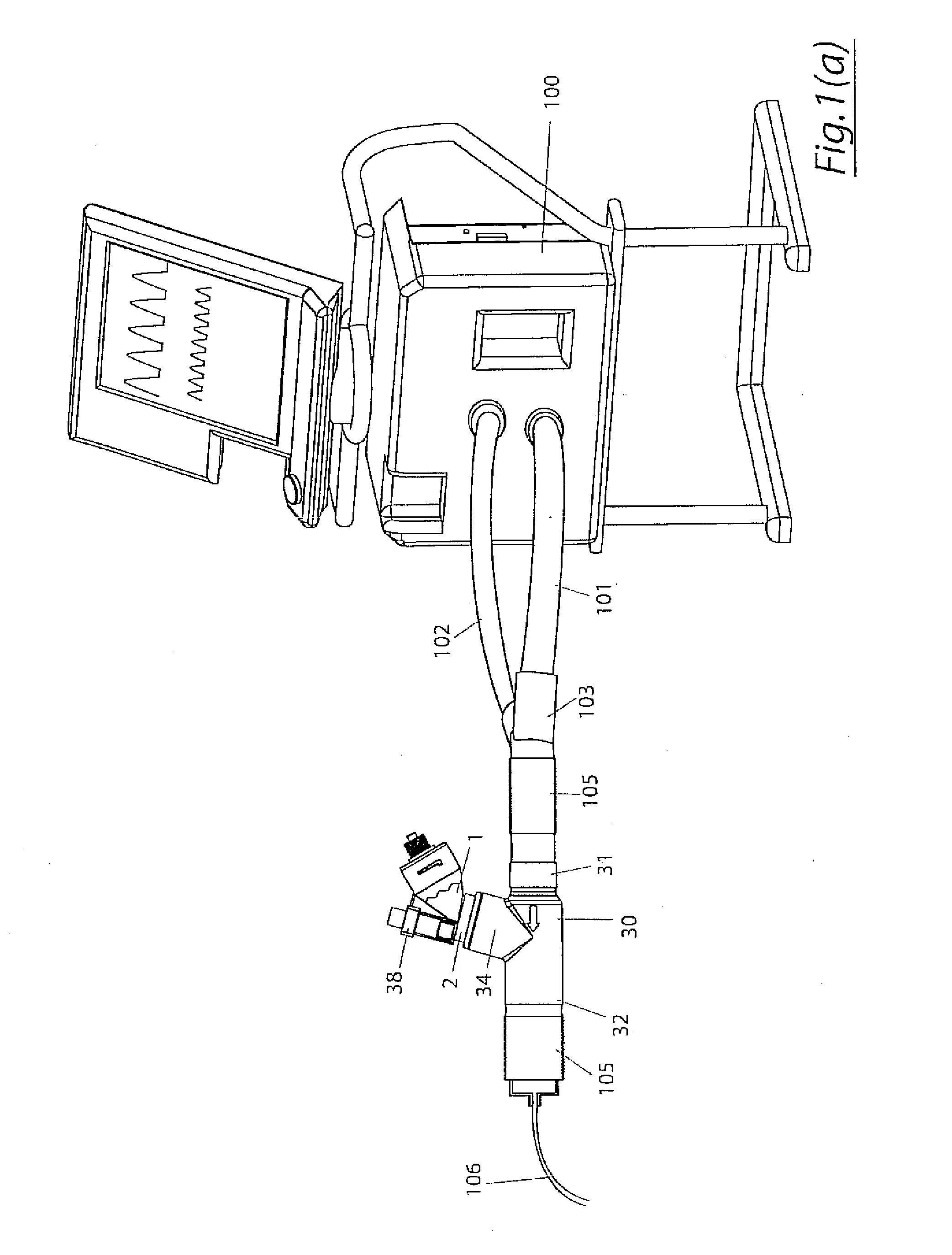
[0073]The humidifying system of the invention is particularly useful in delivering the aerosolised humidifying agent to a patient whose breathing is being assisted by a ventilator 100 as illustrated diagrammatically in FIG. 1A. An inhalation or inspiration line 101 extends from the ventilator 100. A return or exhalation line 102 also extends to the ventilator 100. The inspiration and exhalation lines are connected to a junction piece 103, which may be a wye junction. A patient line 105 extends from the wye 103 to an endotracheal tube 106 which extends to the patients lungs. Generally, the various lines 101, 102, 105, 106 are provided by lengths of plastic tubing which are interconnected. The tubing defines lumen...


PUM


Abstract

A method for humidifying gas in a ventilator circuit 100, 101, 102, 105, 106 comprises aerosolising a humidifying agent such as water or saline using an aerosol generator 2 and delivering the aerosolised humidifying agent to the inspiration line 101 of the ventilator circuit coupled to the respiratory system of a patient. The aerosol generator 2 comprises a vibratable member 40 having a plurality of apertures extending between a first surface and a second surface. A controller 3 controls the operation of aerosol generator 2, for example in response to the flow of air in the inspiration line 101 as detected by a sensor 11.

Description

CROSS-REFERENCES TO RELATED APPLICATIONS[0001]The present application is a continuation-in-part of U.S. patent application Ser. No. 12 / 058,304 filed Mar. 28, 2008 which claims the benefit of U.S. Provisional Application No. 60 / 907,311 filed Mar. 28, 2007.[0002]The present application also claims the benefit of U.S. Provisional Application No. 61 / 100,515 filed Sep. 26, 2008.BACKGROUND OF THE INVENTION[0003]This invention relates to humidification in breathing circuits for intensive care management of mechanically ventilated patients.[0004]During a normal 24 hour period 250-350 ml of water is lost from the respiratory tract.[0005]During normal breathing the upper respiratory tract humidifies and filters the inspired air. This task occurs primarily in the nasopharynx where air is exposed to a large area of highly vascular, moist mucus membrane. On exhalation some of the moisture taken to humidify the air during inspiration is recovered but the balance, the 250-350 ml, is replaced from ...

Claims


Application Information

Patent Timeline
Patent Type & Authority Applications(United States)
IPC IPC(8): A61M16/16
CPCA61B17/3474B05B17/0669A61M13/003A61M15/0085A61M16/1045A61M16/14A61M16/16A61M2016/0039A61M2202/0208A61M2202/0225A61M2202/025A61M2202/0266A61M2202/0291A61M2202/0468A61M2202/048B05B17/0646A61M13/00A61M16/0833B05B12/081
Inventor CLANCY, DERMOT JOSEPHDUFFY, CONOR PAULGIBBONS, KEITHPOWER, JOHN SYLVESTERSMITH, NIALL SCOTT
Owner CLANCY DERMOT JOSEPH
Why Eureka
Try Eureka