Combined heat shield and wire-holding structure for a saddle-type vehicle

a technology of heat shield and wire holding structure, which is applied in the direction of optical signal, cycle equipment, cycle, etc., can solve the problems of vapor lock, difficult to reach some individual wires, and the limited space available for placing other components, so as to achieve convenient wiring work, reduce the weight of the wiring harness, and facilitate the effect of wiring

Active Publication Date: 2009-10-01
HONDA MOTOR CO LTD
View PDF10 Cites 9 Cited by
  • Summary
  • Abstract
  • Description
  • Claims
  • Application Information

AI Technical Summary

Benefits of technology

[0018]According to the above aspect and feature of the present invention, the wire-holding portion is available to hold any cables to be routed longitudinally along the vehicle body in addition to the wiring harness, making for even easier wiring work.
[0019]According to a fourth aspect and feature of the present invention, in addition to any of the first through third aspects and features of the present invention, the wire-holding portion is formed to have a substantially U-shaped cross section opening upwardly, thereby supporting the wiring harness which is routed in the vehicle longitudinal direction from an underside. As such, the weight of the wiring harness can be effectively supported with the heat shield which is mounted so as to straddle across the vehicle body frame sections.
[0020]According to the above aspect and feature of the present invention, the weight of the wiring harness can therefore be effectively supported when the heat shield is mounted so as to straddle across the vehicle body frame sections. The wiring harness can therefore be held in place even more reliably.

Problems solved by technology

If stored fuel is exposed to heat, it may eventually percolate or cause vapor lock.
If the electric wiring harness is routed inside of the vehicle body frame, however, the amount of space available for placing other components is restricted by the space consumed by the wiring.
In addition, routing the wiring harness inside of the vehicle body frame allows for a limited amount of space in which to do wiring work, and may render it difficult to reach some of the individual wires.

Method used


Image

  • Combined heat shield and wire-holding structure for a saddle-type vehicle
  • Combined heat shield and wire-holding structure for a saddle-type vehicle
  • Combined heat shield and wire-holding structure for a saddle-type vehicle

Examples


Embodiment Construction

[0028]An exemplary embodiment of the present invention will now be described, with reference to the drawings. Throughout this description, relative terms like “longitudinal,”“crosswise,”“vertical,” and the like are used in reference to a vantage point of an operator of the vehicle, seated on the driver's seat and facing forward. It should be understood that these terms are used for purposes of illustration, and are not intended to limit the invention.

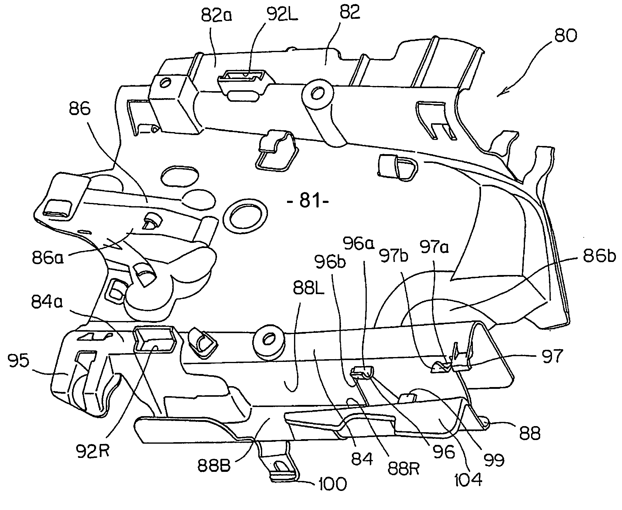
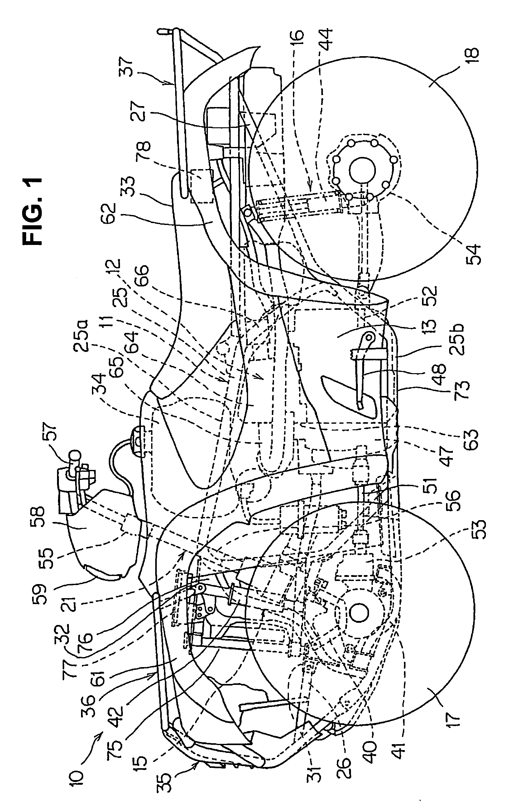
[0029]As shown in FIG. 1, a saddle-type off-road vehicle 10 (hereinafter referred to, simply, as “saddle-type vehicle 10”) includes a vehicle body frame 11, an engine 12, a transmission 13, a front suspension 15, a rear suspension 16, and a steering system 21. Specifically, the engine 12 is mounted at a center lower portion of the vehicle body frame 11. The transmission 13 is connected to the engine 12 and mounted on the vehicle body frame 11. The front suspension 15 and the rear suspension 16 suspend left and right front wheels 17, 17 ...


PUM


Abstract

A combined heat shield and wire-holding structure for a saddle-type vehicle, where the vehicle includes a pair of right and left frame sections extending in a vehicle longitudinal direction, and a fuel tank disposed above the vehicle body frame sections. The combined heat shield and wire-holding structure comprises a heat shield, which is disposed below the fuel tank and which extends between the right and left body frame sections. The combined heat shield and wire-holding structure includes a wire-holding portion which extends in the vehicle longitudinal direction outside of the vehicle body frame, and the wire-holding portion holds a wiring harness routed through an inside portion of the vehicle.

Description

CROSS-REFERENCE TO RELATED APPLICATIONS[0001]The present invention claims priority under 35 USC 119 based on Japanese patent application No. 2008-082963, filed on Mar. 27, 2008. The entire subject matter of this priority document, including specification claims and drawings, is incorporated by reference herein.BACKGROUND OF THE INVENTION[0002]1. Technical Field of the Invention[0003]The present invention relates to a wire-holding structure for a saddle-type vehicle which is capable of supporting a wiring harness routed through an inside portion of the vehicle. More particularly, the present invention relates to a combined heat shield and wire-holding structure which is configured to install a wiring harness at a location between a frame section and a vehicle body cover in a saddle-type vehicle.[0004]2. Background Art[0005]It is generally known that liquid fuel stored in a vehicle fuel tank is best kept at a relatively cool temperature. If stored fuel is exposed to heat, it may event...

Claims


Application Information

Patent Timeline
Patent Type & Authority Applications(United States)
IPC IPC(8): B62D21/00H02B1/20B62J11/19
CPCB62J6/18B62J23/00Y10S180/908B62K5/01B62J35/00B62J11/19
Inventor OSHIMA, TADASHIHOJO, MASAYUKI
Owner HONDA MOTOR CO LTD
Why Eureka
Try Eureka