Filter closure system with bayonet closure

a filter housing and bayonet technology, applied in the direction of filtration separation, machines/engines, separation processes, etc., can solve the problems of dirt particles becoming blocked, and achieve the effect of preventing operating errors, simple way, and simple handling

Inactive Publication Date: 2009-10-01
MANN HUMMEL GMBH
View PDF4 Cites 45 Cited by
  • Summary
  • Abstract
  • Description
  • Claims
  • Application Information

AI Technical Summary

Benefits of technology

[0013]The filter closure system according to the invention has the advantages that in a simple way a seal-tight connection can be produced wherein a simple, self-evident handling is enabled that also prevent operating errors. Moreover, the production and/or disposal can be realized in an inexpensive way. Further advantages of the invention reside in the great load capacity and holding force of the high-strength connection that can be achieved even with minimal mounting forces; a fast mounting and demounting action because, in contrast to conventional screw-on filters, it is not required to perform several turns of the filter for screwing it on or off; the application of the closure system in a very tight space and at minimal cost; and the realization of advantageous metal-free configurations for disposal of used filters including filter housing, filter element and closure system.
[0014]Since, in contrast to the prior art devices, there is no need for a stable terminal disk, i.e., a disk made from metal, with a centrally arranged thread at the end face of the filter in order to screw on the filter onto a threaded socket of the connecting head, it is possible to produce metal-free filters in accordance with the present invention. Therefore, it is possible to design the terminal disks to be significantly weaker, i.e, thinner and/or made ...

Problems solved by technology

The filters or filter elements that are inserted into the filter housing are usually disposable parts because the filter elements not only separate oil that ...

Method used


Image

  • Filter closure system with bayonet closure
  • Filter closure system with bayonet closure
  • Filter closure system with bayonet closure

Examples


Embodiment Construction

[0030]Before describing in detail embodiments that are in accordance with the present invention, it should be observed that the embodiments reside primarily in combinations of apparatus components related to filter closure systems. Accordingly, the apparatus components have been represented where appropriate by conventional symbols in the drawings, showing only those specific details that are pertinent to understanding the embodiments of the present invention so as not to obscure the disclosure with details that will be readily apparent to those of ordinary skill in the art having the benefit of the description herein.

[0031]In this document, relational terms such as first and second, top and bottom, and the like may be used solely to distinguish one entity or action from another entity or action without necessarily requiring or implying any actual such relationship or order between such entities or actions. The terms “comprises,”“comprising,” or any other variation thereof, are inte...


PUM

PropertyMeasurementUnit
Fractionaaaaaaaaaa
Fractionaaaaaaaaaa
Fractionaaaaaaaaaa

Abstract

A filter closure system has a connecting end at an end face of a cylindrical filter housing and a connecting head matching the connecting end. The connecting end is insertable axially into the connecting head and connected positive-lockingly to the connecting head by an insertion-rotation movement. Connecting end and connecting head have a bayonet connection with receiving slots or receiving projections and matching insertion projections. The matching insertion projections engage the receiving slots or projections when the bayonet connection is closed. The receiving slots or projections and the insertion projections each are arranged substantially in a perpendicular plane relative to the insertion direction. The receiving slots or projections are elongate and circumferentially do not extend completely around but are segmented. The receiving slots or projections are sequentially arranged in the insertion direction and are substantially parallel to one another. The insertion projections are also sequentially arranged in the insertion direction.

Description

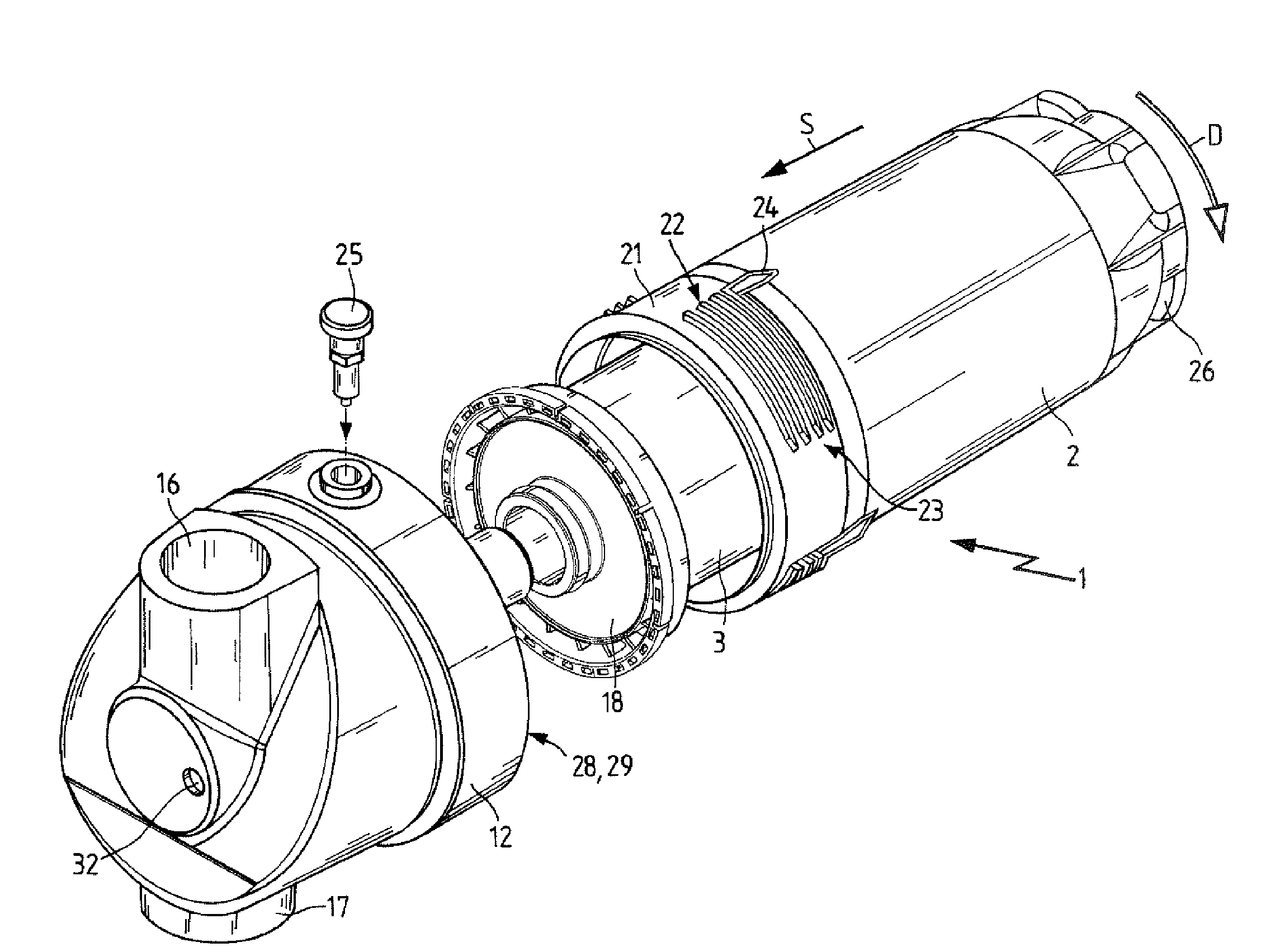
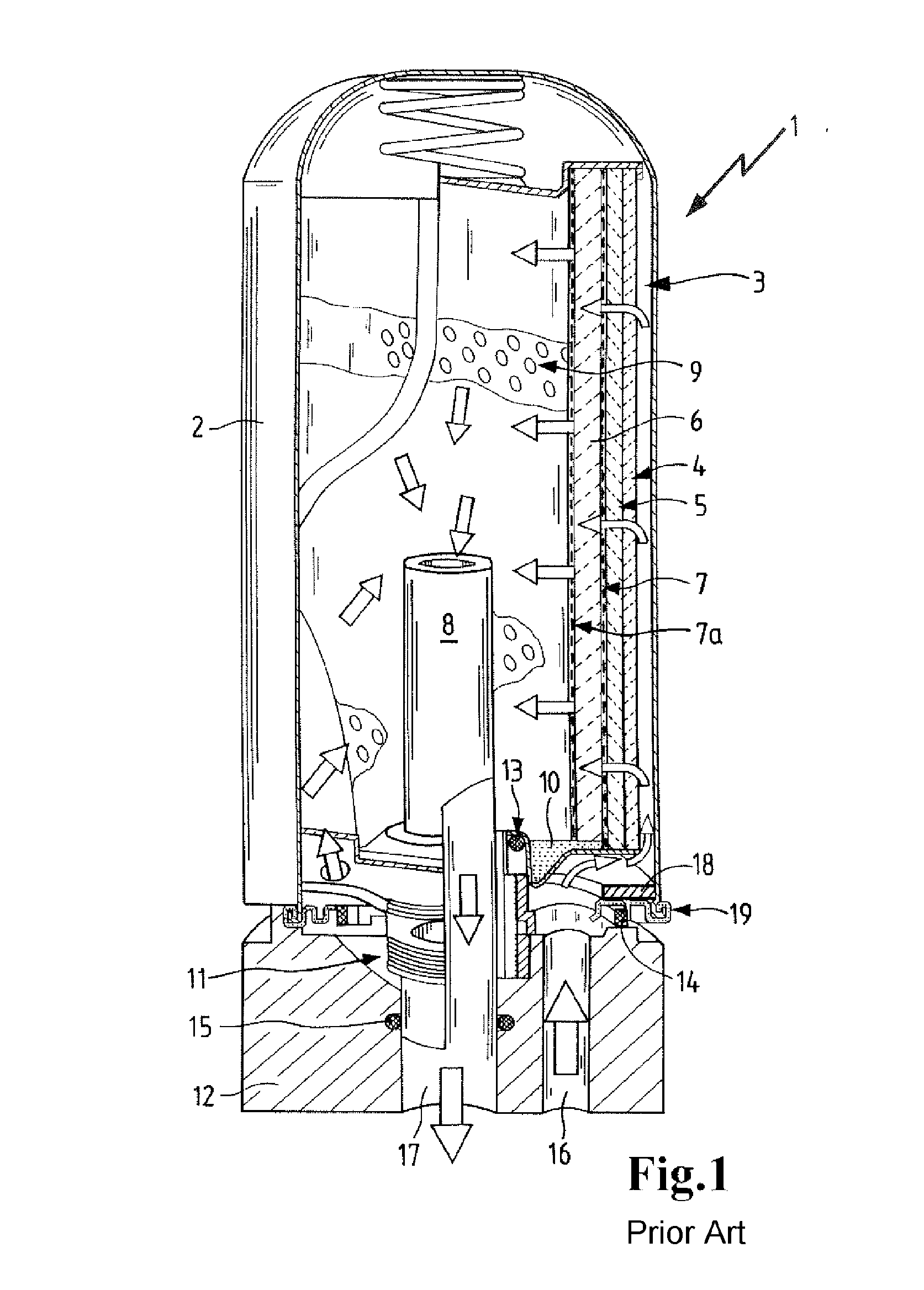
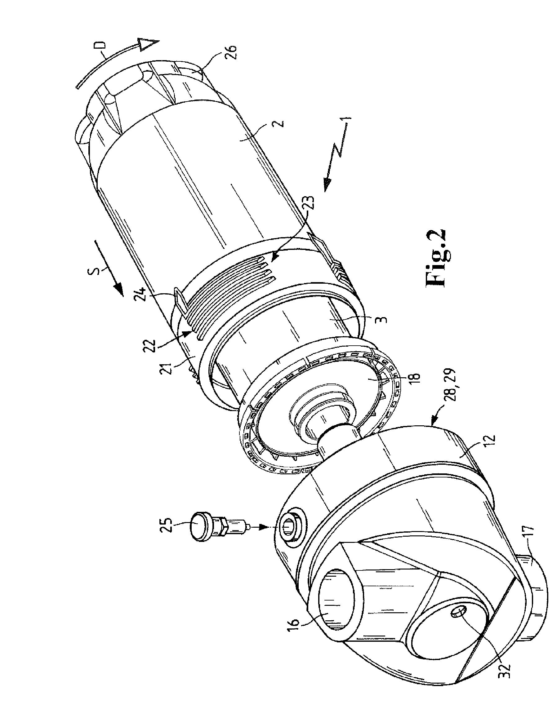
CROSS REFERENCE TO RELATED APPLICATIONS[0001]This application claims the benefit under 35 USC 119 of the earlier filing date of foreign application DE 20 2008 004 289.5 filed in Germany on Mar. 27, 2008.TECHNICAL FIELD[0002]The invention relates to filter housing and filter closure systems for filter housings.BACKGROUND OF THE INVENTION[0003]The invention relates to a filter closure system for seal-tightly connecting a connecting end at the end face of a of circular cylindrical shaped filter housing to a connecting head that matches the connecting end and into or onto which the connecting end is insertable or attachable in an axial insertion direction and, by an insertion-rotation movement, is connectable positive-lockingly to the connecting head. The connecting end and the connecting head have at least at one connecting location a bayonet connection. The bayonet connection in or on one of the two connected parts includes a receiving slot or a receiving projection that is arranged s...

Claims


Application Information

Patent Timeline
IPC IPC(8): B01D29/00B01D21/30F02M37/32
CPCB01D35/30B01D46/0005B01D2201/4015B01D2201/4046F02M37/22B01D2265/05F01M13/04F01M2013/0438B01D2265/022F02M37/32
Inventor MUENKEL, KARLHEINZDWORATZEK, KLEMENSPETSCHL, THOMASBECKER, STEFANNGUYEN, DUC CUONG
Owner MANN HUMMEL GMBH
Why Eureka
Try Eureka